Welding method for winding rotors and head combining sleeve

A welding method and winding rotor technology are applied in welding equipment, metal processing equipment, manufacturing tools, etc., which can solve the problems of large overall thickness, waste of solder, and damage to coil insulation, and achieve reduced rotor failure, good process reliability, and The effect of short welding time

Inactive Publication Date: 2016-09-28
NANTONG JINCHI MECHANICAL ELECTRIC
View PDF9 Cites 2 Cited by
  • Summary
  • Abstract
  • Description
  • Claims
  • Application Information

AI Technical Summary

Problems solved by technology

Generally speaking, the joint part of the rotor has three layers in the thickness direction, and the overall thickness is relatively large. Traditional welding is not easy to penetrate, and the joint head surface is heated unevenly. After melting, the silver solder flows into the high temperature place in large quantities and enters the coil insulation part. Low temp

Method used


Image

  • Welding method for winding rotors and head combining sleeve
  • Welding method for winding rotors and head combining sleeve

Examples


Embodiment Construction

[0017] The present invention will be further described below in conjunction with specific drawings and embodiments.

[0018] The welding method of the wound rotor joint head includes the following process steps:

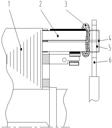
[0019] Step 1, such as figure 1 As shown, after the rotor coil 2 of the motor is embedded in the rotor core 1 and bent and reshaped, the end of the rotor coil 2 of the motor is covered with a parallel cap 5, and a parallel wedge 4 is embedded in the middle of the two rotor coils 2 of the motor. Tighten the headgear 5; then hoist the rotor to the welding workbench and place it horizontally;

[0020] Step two, such as figure 1 As shown, a circle of asbestos rope 3 soaked in water is wrapped around the insulation of the motor rotor coil 2 and the adjacent part of the headgear 5 as the welding protection of the motor rotor coil 2, so as to prevent the insulation of the motor rotor coil 2 from burning out;

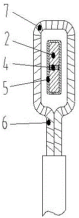
[0021] Step 3: Wrap one or two layers of glass ribbon 7 on th...


PUM


Abstract

The invention relates to a welding method for winding rotors and a head combining sleeve and belongs to the field of motor manufacturing processes. According to the welding method, motor rotor coils are embedded in a rotor iron core, end heads of the motor rotor coils are sleeved with a head combining sleeve; then the rotors are hoisted onto a welding workbench and horizontally placed; the insulating portions, close to the head combining sleeve, of the motor rotor coils are wrapped by a circle of waterishlogged asbestos rope; an electrode holder is wrapped by one to two layers of glass tapes; then the electrode holder clamps the head combining sleeve; welding is performed through a medium-frequency welding machine; before the head combining sleeve becomes completely red, a silver solder with the silver content being 15% is used for painting a gap between the head combining sleeve and the motor rotor coils one time; and after the head combining sleeve becomes completely red, the gap between the head combining sleeve and the motor rotor coils and the end faces of the head combining sleeve and the motor rotor coils are uniformly and smoothly painted with silver solder and soldering flux. The welding method achieves the purposes that the welding time is short, the work efficiency is high, insulating damage is small, welding is thorough, and process reliability is good.

Description

[0001] technical field [0002] The invention relates to a welding method for parallel ends of wound rotors, which belongs to the field of motor manufacturing technology. It has great practical value for the production and manufacture of wound rotors. Background technique [0003] Wound rotor motors are widely used in industrial and agricultural production because of their excellent starting and speed regulating performance. At the same time, because its structure is more complicated than that of the cage rotor motor, maintenance is more troublesome, so higher requirements are put forward for the manufacturing process and manufacturing quality of the motor. In addition to the common problems of brush sparks and brush lifting short-circuit device failures, quality problems caused by unreliable welding of rotor coils and headgears also account for a large proportion. [0004] With the same welding thickness, intermediate frequency welding requires less welding current than...

Claims


Application Information

Patent Timeline
IPC IPC(8): B23K31/02
CPCB23K31/02
Inventor 向翰
Owner NANTONG JINCHI MECHANICAL ELECTRIC
Why Eureka
Try Eureka