
Powerful suction-type sewer scavenger

A sewage suction truck, a powerful technology, applied in fixed filter elements, filtration separation, construction, etc., can solve the problems of low cleaning efficiency, increased traffic pressure and pollution, and affecting the treatment capacity of sewage plants, etc.

Inactive Publication Date: 2016-09-28
重庆耐德山花特种车有限责任公司
View PDF10 Cites 3 Cited by
  • Summary
  • Abstract
  • Description
  • Claims
  • Application Information

AI Technical Summary

Problems solved by technology

[0005] 1. The overall cleaning efficiency is low
[0006] Although the suction efficiency is high, due to the limited volume of the tank, more water and less slag, multiple suctions and multiple transportations are required to complete the coarse slag cleaning operation. The operation is not continuous and the transportation takes a long time (the farther the sewage plant is, the more prominent), resulting in low overall cleaning efficiency
[0007] 2. High cost, increased traffic pressure and pollution
[0008] In order to complete the cleaning operation, multiple transportations are required, and the transportation cost is high
Because the transportation needs to go through urban roads, the traffic flow will increase, the exhaust gas emitted by the vehicles and the dripping and throwing caused by the sealing failure may occur, which will increase the environmental pollution.
[0009] 3. Increase the pressure of pretreatment equipment such as coarse screens in the sewage plant, affecting the treatment capacity of the sewage plant

Method used


Image

  • Powerful suction-type sewer scavenger
  • Powerful suction-type sewer scavenger
  • Powerful suction-type sewer scavenger

Examples


Embodiment Construction

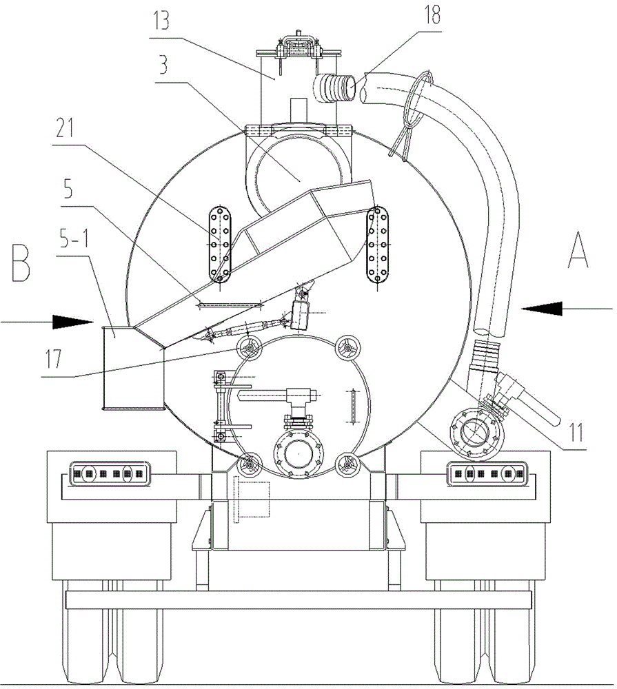
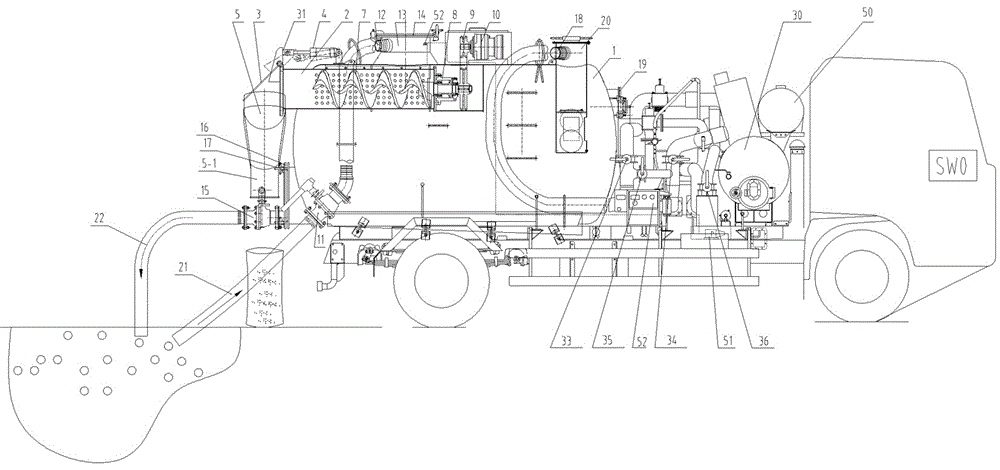
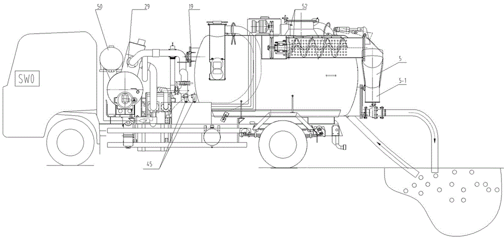
[0051] see Figure 1 to Figure 8 , a powerful sewage suction vehicle, comprising a sewage suction vehicle body, the chassis of the sewage suction vehicle body is provided with a tank body forming a closed space, the tank body is provided with a feeding port and a vent port, and the tank body is provided with There is a solid-liquid separation filter cartridge. The solid-liquid separation filter cartridge is fixed on the upper part of the tank body, one shaft end of the solid-liquid separation filter cartridge protrudes from the rear end of the tank body to form a discharge port, and the shaft end of the solid-liquid separation filter cartridge extends out of the tank body The end is provided with a sealing cover to seal the discharge port. The shaft end of the solid-liquid separation filter cartridge located in the tank is provided with an end plate. The solid-liquid separation filter cartridge is provided with a shaftless spiral body. The through hole provided on the end pla...


PUM


Abstract

The invention relates to a powerful suction-type sewer scavenger. The powerful suction-type sewer scavenger comprises a suction-type sewer scavenger body, wherein a tank body forming closed space is arranged on a chassis of the suction-type sewer scavenger body and provided with a feeding port I, a vent nozzle and a vacuum pumping port; a solid-liquid separation filter cartridge is arranged in the tank body; one axial end of the solid-liquid separation filter cartridge extends out of the rear end of the tank body; a seal cover is arranged at the axial end, extending out of the tank body, of the solid-liquid separation filter cartridge; an end plate is arranged at the axial end, located in the tank body, of the solid-liquid separation filter cartridge; a shaftless screw body is arranged in the solid-liquid separation filter cartridge; a support end of the shaftless screw body penetrates a via hole formed in the end plate of the solid-liquid separation filter cartridge, extends out of the solid-liquid separation filter cartridge and is connected with a power driving device through a transmission mechanism; a plurality of filter holes and a feeding port II are formed in the body, located in the tank body, of the solid-liquid separation filter cartridge; the feeding port II allowing entry of sewage is communicated with the feeding port I of the tank body; a liquid level control device is arranged in the tank body; a first filter device is communicated between the vacuum pumping port and a first vacuum pump through a pipeline.

Description

technical field [0001] The invention relates to the field of environmental protection, in particular to a powerful sewage suction truck. Background technique [0002] The utility model patent with the application number of 201320633106.6 discloses a sewage suction truck, which uses the principle of negative pressure pneumatic conveying to suck powder, solid, sludge, etc. into the recovery tank, which is far more powerful than ordinary vacuum suction trucks. Attractive (high suction, long horizontal distance, fast suction speed), simple operation, convenient maintenance and other characteristics, used for the recovery of various sludge, feces and dust. It can be applied to the suction, shipment and discharge of sludge in rainwater wells, inspection wells, sedimentation wells and various ditches, septic tank waste and feces, and sludge in sewage pools. It can also be used for loading garbage stations, garbage Compress liquid wastes such as leachate and industrial hazards, and...

Claims


Application Information

Patent Timeline
IPC IPC(8): E03F7/10B01D29/94B01D29/11
CPCB01D29/117B01D29/94E03F7/10E03F7/106
Inventor 周涛杨增玉屈冲冲陈明进汪军邓宜荣
Owner 重庆耐德山花特种车有限责任公司
Learn More