Hot press installation method of engine gas mixer and cam structure

A gas mixer and engine technology, which is applied to engine components, combustion engines, machines/engines, etc., can solve the problems of easily damaged cam devices, bulky, and insufficient precision in controlling the opening of the oil needle, so as to achieve no position change, Safe and reliable operation, the effect of optimal idle performance

Active Publication Date: 2018-10-02
ZHEJIANG SEEYES IND CO LTD
View PDF7 Cites 0 Cited by
  • Summary
  • Abstract
  • Description
  • Claims
  • Application Information

AI Technical Summary

Problems solved by technology

[0003] The current gas engine generally uses a vehicle gas mixer, which has the following problems in the process of use: the vehicle gas mixer has a complex structure and a large volume, and it is difficult to meet the weight and volume requirements of hand-held tools.
Third, due to the great difference in physical properties between liquid fuels such as gasoline and gaseous fuels, the throttle opening and oil needle opening height control devices of the rotary valve of the mixer need special design and matching
Fourth, there are obvious shortcomings in the traditional mixer to control the opening height of the oil needle. Some are designed at the bottom of the suspension structure where the throttle cable is fixed, and the lift of the plunger is controlled by the top block fixed on the mixer shell. , and some are fixed in the plunger groove of the mixer shell by glue or riveting. Some of these methods are not accurate enough to control the opening of the oil needle, and some are prone to failure due to time, temperature changes and mechanical vibration. Traditional The interference fit of the normal temperature press fit is easy to damage the cam device, and it is difficult to mass produce
For this reason, many manufacturers and scientific research institutes have carried out development and research, but no satisfactory products have come out so far.

Method used


Image

  • Hot press installation method of engine gas mixer and cam structure
  • Hot press installation method of engine gas mixer and cam structure
  • Hot press installation method of engine gas mixer and cam structure

Examples


Embodiment Construction

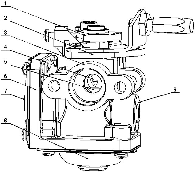
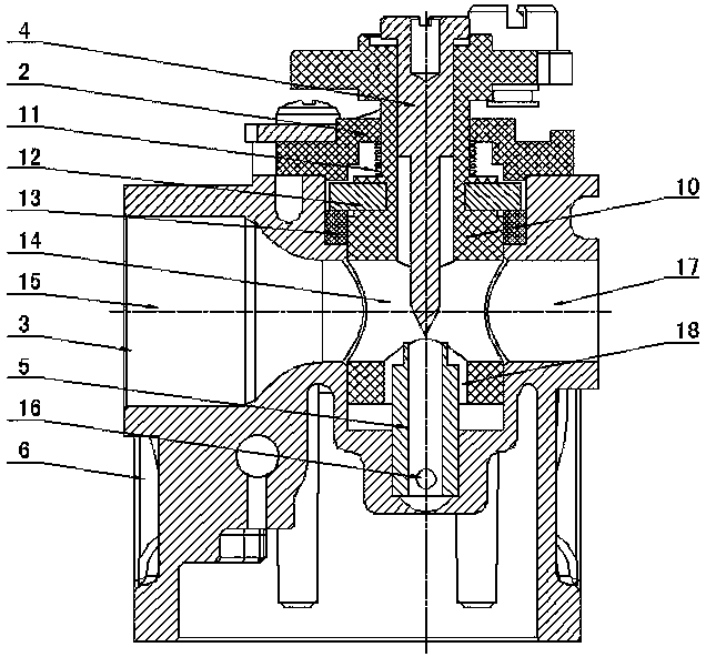
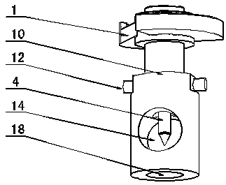
[0020] figure 1 with figure 2 As shown, the present invention creates a specific embodiment of the engine gas mixer, which includes a housing 6, a gland 2, a throttle plunger assembly, and the housing 6 is provided with a venturi tube 3, a high-pressure chamber 7, The low-pressure chamber 8 and the air intake chamber 9, the throttle plunger assembly is installed on the plunger installation hole of the housing 6 through the gland 2, and the throttle plunger assembly includes the throttle plunger 10, left and right guide posts 12. Oil needle 4, the throttle plunger 10 is provided with a plunger vent hole 14 matched with the venturi tube 3 and forms a rotary valve with the venturi tube 3, and the oil needle 4 is fixed in the center hole of the throttle plunger 10 Above, the left and right guide posts 12 are symmetrically fixed on both sides of the throttle plunger 10, and a cam structure 13 is fixed on the plunger mounting hole of the housing 6 through interference fit, and the...


PUM

PropertyMeasurementUnit
lengthaaaaaaaaaa
diameteraaaaaaaaaa
diameteraaaaaaaaaa

Abstract

The invention discloses a fuel gas mixer of an engine and a hot-pressing installation method of cam structures. The fuel gas mixer comprises a shell (6), a pressing cover (2) and a throttle valve plunger assembly; the throttle valve plunger assembly comprises a throttle valve plunger (10), left and right guide columns (12) and an oil needle (4), the throttle valve plunger (10) is provided with a plunger air hole (14) and forms a rotary valve with a venturi pipe (3), the oil needle (4) is fixed to the throttle valve plunger (10), and the left and right guide columns (12) are symmetrically fixed to the two sides of the throttle valve plunger (10); the shell (6) is fixedly provided with the cam structures (13), the left and right guide columns (12) are arranged on the cam structures (13), and springs (11) are arranged between the throttle valve plunger (10) and the pressing cover (2); the shell (6) is fixedly provided with a main spraying pipe (5), the main spraying pipe (5) extends into a plunger throat (18) of the throttle valve plunger (10), and a pointer valve of the oil needle (4) and the main spraying pipe (5) are matched for forming a fuel gas valve. According to the structure, the fuel gas mixer has the advantages that the structure is simple and reasonable, the operation is stable, use is safe, the noise is low, the air-fuel ratio is good, the low-temperature starting performance is good, and the environment protection performance is good.

Description

technical field [0001] The invention relates to an auxiliary part of a gas engine, in particular to an engine gas mixer with an automatic precise ratio of air and gas and a hot-pressing installation method for a cam structure. Background technique [0002] As we all know, garden tools have a vast market, and the market demand is huge. More and more manufacturers focus on garden tools. With the strengthening of environmental protection awareness, new emission regulations are constantly being introduced, and handheld garden tools that use clean, environmentally friendly, economical and practical gas instead of gasoline as fuel have emerged, such as propane engines. Compared with gasoline engines, propane engines have the unique advantages of stable operation, low noise, long service life, good fuel economy, safety and reliability, good low-temperature start-up performance, green environmental protection, convenience and practicality, and wide application, and can be widely use...

Claims


Application Information

Patent Timeline
Patent Type & Authority Patents(China)
IPC IPC(8): F02M21/04B23P11/02
CPCB23P11/025F02M21/047Y02T10/30
Inventor 胡婷婷其他发明人请求不公开姓名
Owner ZHEJIANG SEEYES IND CO LTD
Why Eureka
Try Eureka