An exhaust hot air drying system

A technology of hot air drying and exhaust fan, applied in the directions of drying gas arrangement, drying, drying machine, etc., can solve the problems of difficult system matching and adjustment, high cost of environmental protection and hidden safety hazards, etc., and optimize the equipment pipeline structure. , keep clean, ensure the effect of safe production

Active Publication Date: 2018-10-30
VERBOCA ENERGY SAVING TECH CO LTD
View PDF9 Cites 0 Cited by
  • Summary
  • Abstract
  • Description
  • Claims
  • Application Information

AI Technical Summary

Problems solved by technology

[0009] The technical problem to be solved by the present invention is to provide an exhaust hot air drying system, which can fundamentally achieve the purpose of energy saving and emission reduction, and at the same time effectively solve the problems of traditional drying systems such as difficulty in system matching and adjustment, excessive exhaust air volume, heating Excessive energy consumption, potential safety hazards, and high cost of environmental protection

Method used


Image

  • An exhaust hot air drying system
  • An exhaust hot air drying system
  • An exhaust hot air drying system

Examples


Embodiment 1

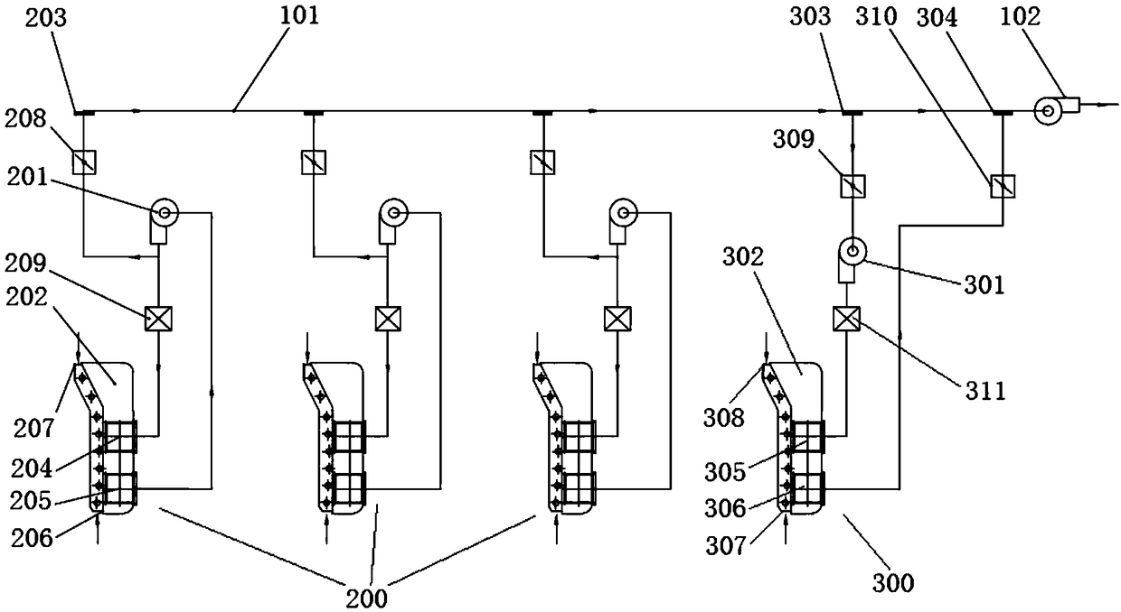
[0028] Embodiment 1: Taking the gravure printing machine as an example, see figure 1 , to describe the implementation of the exhaust hot air drying system:

[0029]The exhaust hot air drying system of this embodiment includes an exhaust main pipe 101, an exhaust fan 102 and at least two groups of first drying units 200, and the exhaust fan 102 is arranged at the tail end of the exhaust main pipe 101; A drying unit 200 includes a first unit blower 201 and a first drying box 202, the first drying unit 200 is provided with a first unit air outlet 203, and the first drying box 202 is provided with a first drying box inlet The tuyere 204, the first drying box air outlet 205, the first drying box inlet 206 and the first drying box outlet 207, wherein the first drying box inlet 206 and the first drying box outlet 207 can be used as The fresh air inlet of the first drying unit 200, each group of first drying units 200 is connected to the exhaust main pipe 101 in turn through the firs...

Embodiment 2

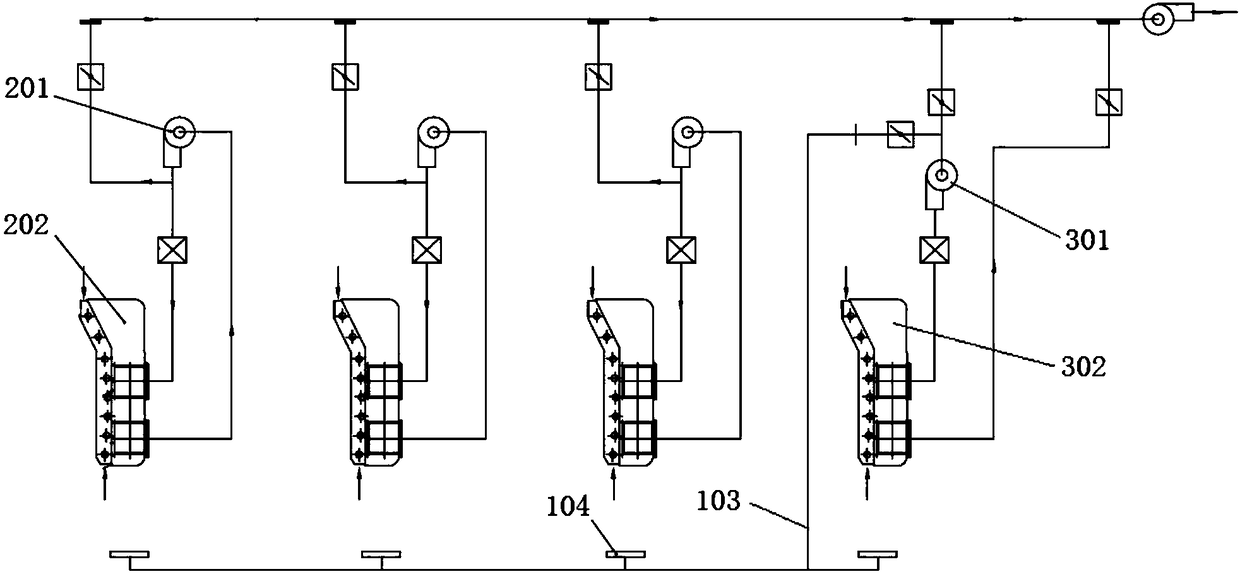
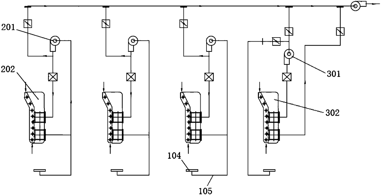
[0039] Embodiment 2: Taking the gravure printing machine as an example, see figure 2 and image 3 , to describe the implementation of the exhaust hot air drying system with an air intake form that takes into account the leakage of the printing unit exhaust gas or the exhaust gas discharge of the volatile solvent of the ink tank:

specific Embodiment approach

[0040] The exhaust hot air drying system described in Embodiment 1 and the improved Embodiment 1 is simply and directly from the outside of the system by the first drying box inlet 206 and the first drying box outlet 207 as the fresh air inlet. Environmental air intake, and in embodiment 2, also possess the air intake form that takes into account printing unit exhaust gas leakage or ink tank volatile solvent exhaust gas discharge, this air intake form includes following two specific implementation modes: the first one, such as figure 2 As shown, on the basis of the above-mentioned embodiment 1, the exhaust air hot air drying system also includes an air collection main pipe 103 and a plurality of air collection grooves 104, and the air collection grooves 104 are arranged in parallel on the air collection main pipe 103 and correspond to each other. Arranged near each of the first drying box 202 and the second drying box 302, the tail end of the air collection main pipe 103 is c...


PUM


Abstract

The invention provides an exhaust hot air drying system. The exhaust hot air drying system comprises an exhaust manifold, an exhaust fan and at least two first drying units, wherein the exhaust fan is arranged at the tail end of the exhaust manifold; the first drying units comprise first unit air supply fans and first drying boxes, and are provided with first unit exhaust holes; the first drying boxes are provided with first drying box air inlets, first drying box air outlets, first drying box feed inlets and first drying box discharge holes; the first drying units are sequentially connected on the exhaust manifold through the first unit exhaust holes; air outlets of the first unit air supply fans are connected with the first drying box air inlets; the air outlets of the first unit air supply fans are connected with the first unit exhaust holes; and the first drying box air outlets are connected with air inlets of the first unit air supply fans. The exhaust hot air drying system can radically achieve the purpose of energy conservation and emission reduction, and has the advantages that the system is concise and stable, the adjustment is simple, the exhaust volume is small, the energy consumption is low, the potential safety hazard is avoided, the environmental protection treatment cost is low, and the like.

Description

technical field [0001] The invention belongs to the technical field of energy saving and emission reduction, and relates to a multi-unit hot air drying process in industries such as packaging and printing, coating and coating, and is specifically applied to production equipment requiring hot air drying such as gravure printing machines, compound machines, coating machines, and furniture spray paints. . Background technique [0002] The drying system is the main energy consumption unit of printing, compounding, coating, spraying and painting production equipment, and it is also the main emission source of exhaust gas. The efficiency of the drying system is the core parameter of the production equipment performance evaluation index. [0003] At present, the drying system of most production equipment does not have a good automatic control function. During operation, the operator relies on the operator to manually adjust the operating state of the drying system based on practica...

Claims


Application Information

Patent Timeline
Patent Type & Authority Patents(China)
IPC IPC(8): F26B21/00
CPCF26B21/001F26B21/004
Inventor 简甦段元敏
Owner VERBOCA ENERGY SAVING TECH CO LTD
Why Eureka
Try Eureka