
Current detection method of one-phase inversion grounding device

A grounding device and current detection technology, which is applied in the direction of measuring devices, measuring current/voltage, and responding to fault current protection, etc., can solve problems such as reducing power supply reliability, high insulation requirements, and difficult line selection for arc suppression coil faults , to eliminate the effect and improve the accuracy of current detection

Inactive Publication Date: 2016-09-28
CHANGSHA UNIVERSITY OF SCIENCE AND TECHNOLOGY
View PDF6 Cites 3 Cited by
  • Summary
  • Abstract
  • Description
  • Claims
  • Application Information

AI Technical Summary

Problems solved by technology

The neutral point ungrounded system can still run with the fault for 1~2 hours after a single-phase ground fault occurs, and the power supply reliability is high, but the insulation of each phase must be based on the phase voltage. Double-fold design, which requires high insulation; the neutral point through the arc suppression coil grounding system can effectively reduce the ground fault current, but it can only compensate for the fault current of the power frequency, and the connection of the arc suppression coil will lead to fault selection When a ground fault occurs in a small-resistance grounding system, the short-circuit current is very large, and the relay protection device will act at the moment of the fault to cut off the faulty line, but at the same time it also reduces the power supply reliability of this method

Method used


Image

  • Current detection method of one-phase inversion grounding device
  • Current detection method of one-phase inversion grounding device
  • Current detection method of one-phase inversion grounding device

Examples


Embodiment Construction

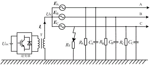
[0020] figure 1 is a topological diagram of a single-phase inverter grounding device, , , is the three-phase power supply of the power distribution system, , , , , , Respectively represent three-phase ground resistance and capacitance, R d Indicates the grounding resistance when a single-phase ground fault occurs, U N is the neutral point voltage of the system. The single-phase inverter-type grounding system is grounded through an active inverter, and the inverter is powered by a DC power supply U DC Power supply, through PWM inverter to generate injection current with controllable amplitude and phase I i Inject into the neutral point, T means inject into the transformer.

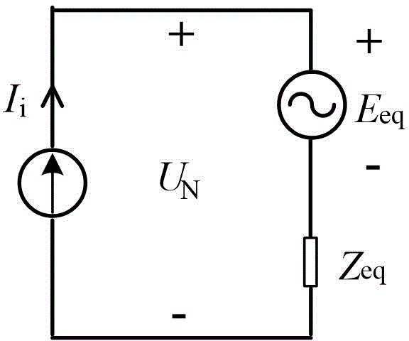
[0021] figure 2 It is the equivalent circuit diagram of the new grounding device and distribution network. Since the active inverter circuit is fully controllable, it can be equivalent to a controllable current source, and the three-phase power supply of the distribution networ...


PUM


Abstract

The present invention discloses a current detection method of a one-phase inversion grounding device. The main body of the device is a one-phase inverter which is connected between the neutral point of a power distribution network and the ground. In the condition of the normal operation of an electric system, two power frequency current with the same injection amplitude and different phase angles are injected into the neutral point of the power distribution network at different times through an inversion circuit, the neutral point voltage value when the current is injected twice is measured in real time, and the power distribution network grounding parameters (power distribution network equivalent impedance and equivalent electromotive force) are calculated, so that the amplitudes and the phases of the power distribution network fault arc extinguishing and the three-phase imbalance compensation current. The current is injected to the neutral point to inhibit the grounding fault arc and maintain the three-phase voltage balance. The current detection method of the one-phase inversion grounding device can be enforced when the system is normally operated so as to effectively avoid the influence of the transient process on the detection precision at the occurrence of the grounding fault; and moreover, the current detection method of the one-phase inversion grounding device only needs to inject current into the neutral point twice to realize the current detection, with high timeliness and simple realization.

Description

technical field [0001] The invention relates to a current detection method of a single-phase inverter type grounding device, which is particularly suitable for related fields such as single-phase grounding faults of distribution networks and three-phase unbalanced overvoltage suppression. Background technique [0002] The distribution network is at the terminal of the power system, has a complex and changeable structure, and is closely connected with users, which easily leads to various faults. Single-phase ground fault is the most common fault in the distribution network. When the fault current is too large, arc light will be generated, and the arc combustion will bring great harm such as fire and equipment damage. Three-phase unbalanced voltage is a long-term existence in the distribution network. It is difficult to solve the problem completely. The existence of three-phase unbalanced overvoltage will affect the normal operation of single-phase loads in the distribution ne...

Claims


Application Information

Patent Timeline
IPC IPC(8): G01R19/00H02H3/16H02J3/26
CPCY02E40/50
Inventor 王文贺蕾思思蔡演存曾祥君刘鹏周丰
Owner CHANGSHA UNIVERSITY OF SCIENCE AND TECHNOLOGY
Learn More