Multi-component seismic data least squares reverse time migration imaging method and system

A technology of reverse time migration imaging and least squares, applied in the field of geophysical exploration, can solve problems such as low resolution, imaging errors, and imperfections

Active Publication Date: 2016-09-28
CHINA UNIV OF PETROLEUM (EAST CHINA)
View PDF12 Cites 26 Cited by
  • Summary
  • Abstract
  • Description
  • Claims
  • Application Information

AI Technical Summary

Problems solved by technology

For the migration method of multi-component seismic data based on the acoustic wave equation, this implementation ignores the vector characteristics of the multi-component data, resulting in the neglect of the property information of the subsurface medium, which will inevitably lead to imaging errors
In addition, the separation of P- and S-waves for multi-component seismic data is often not perfect, and this incomplete separation will inevitably lead to crosstalk artifacts in the migration section
For the migration method of multi-component seismic data based on the elastic wave equation, problems such as crosstalk between longitudinal and transverse waves and polarity reversal of shear waves affect the migration accuracy in different degrees and aspects
In addition, there is an error in the wave field continuation operator used in reverse time migration. It is not the exact inverse of the wave field forward continuation operator, but uses the adjoint operator to replace
In addition, the actual seismic data is incomplete, the acquisition aperture is limited, and there are aliases and noises in the data. Combining these factors, the reverse time migration section has acquisition footprints, low resolution, uneven amplitude, and serious artifacts. And other issues
Therefore, the conventional elastic wave reverse time migration method cannot well realize high-precision, high-resolution, signal-to-noise ratio, and amplitude-preserving imaging of multi-component seismic data.

Method used


Image

  • Multi-component seismic data least squares reverse time migration imaging method and system
  • Multi-component seismic data least squares reverse time migration imaging method and system
  • Multi-component seismic data least squares reverse time migration imaging method and system

Examples


example 1

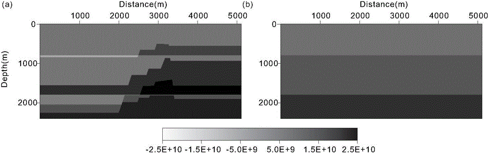
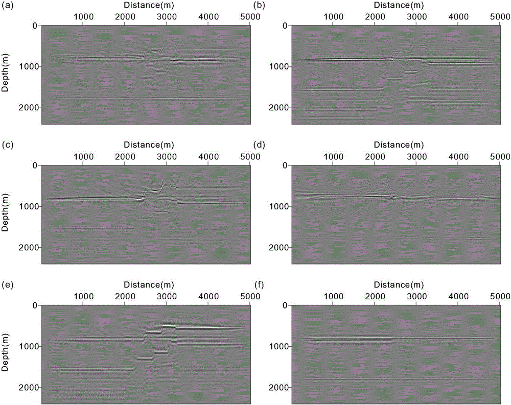
[0147] figure 2 is a two-dimensional steep angle fault model diagram; where, figure 2 (a) is the Lame constant λ model; figure 2 (b) is a model of Lamé's constant μ. 49 explosion sources are set on this model, the source wavelet is set as Lake wavelet, the main frequency is 15 Hz, the initial source point is located at (150m, 100m), and the shot interval is 100m. The receiving observation system on both sides of the middle shot is adopted, the maximum offset distance of one side is 2300m, the minimum offset distance is 150m, and the track spacing is 10m. yes image 3 yes figure 2 The multi-shot stacked migration section of the 2D steep-dipping fault model shown: where, image 3 (a) is the horizontal component profile obtained by traditional methods, image 3 (b) is the vertical component profile obtained by the traditional method, image 3 (c) is the PP profile obtained by traditional methods, image 3 (d) is the PS profile obtained by the traditional method, ima...

example 2

[0149] Image 6 is the Marmousi-ii model: where, Image 6 (a) is the Lame constant λ model; Image 6 (b) is the Lamé constant μ model. This model is one of the international standard models to verify the imaging effects of various migration methods. Set up 47 explosion sources on this model, the source wavelet is set as Lake wavelet, the main frequency is 15 Hz, the initial source point is located at (100m, 100m), and the shot interval is 200m. The receiving observation system on both sides of the middle shot is adopted, the maximum offset distance of one side is 3500m, the minimum offset distance is 100m, and the track spacing is 10m. Figure 7 yes Image 6 The multi-shot stacked migration section of the Marmousi-ii model shown: where, Figure 7 (a) is the horizontal component profile obtained by traditional methods; Figure 7 (b) is the vertical component profile obtained by traditional methods; Figure 7 (c) is the PP profile obtained by traditional methods; Figure...

example 3

[0151] Figure 8 is the SEG / EAGE Salt model: where, Figure 8 (a) is the longitudinal wave velocity model; Figure 8 (b) is the shear wave velocity model. This model is one of the international standard salt dome models to verify the imaging effects of various migration methods. 39 explosion sources are set on this model, the source wavelet is set as Reck wavelet, the main frequency is 12 Hz, the initial source point is located at (170m, 100m), and the shot interval is 150m. The receiving observation system on both sides of the middle shot is adopted, the maximum offset distance of one side is 4800m, the minimum offset distance is 170m, and the track spacing is 10m. Figure 9 yes Figure 8 The multi-shot stacked migration section of the SEG / EAGE Salt model shown: where, Figure 9(a) is the PP profile obtained by traditional methods; Figure 9 (b) is the PS profile obtained by the traditional method (corrected for polarity inversion); Figure 9 (c) is the PP profile util...


PUM


Abstract

The invention discloses a multi-component seismic data least squares reverse time migration imaging method and system. The method conducts modification on the basis of the elastic wave reverse time migration method, directly with the multi-component data as input, under the framework of inversion, employs different wave-field propagators and new imaging conditions at different steps of migration so as to achieve multi-component seismic data migration imaging based on inversion. According to the invention, the thought of inversion is introduced to elastic wave reverse time migration, compared with regular elastic wave reverse time migration, a prestack depth migration profile having high precision, high resolution, high signal to noise ratio, and amplitude preservation can be acquired. The method can effectively overcome lineups destructive interference caused by transverse wave polarity-reversal, and can effectively eliminate migration illusion caused by crosstalk among longitudinal and transverse waves while longitudinal and transverse wave vector characteristics, amplitude and phase characteristics are maintained in entirety. The method increases imaging precision, is applicable to multi-component seismic data migration of all kinds of complex medium models, has clear imaging profiles, and is easy for later-stage geology interpretation.

Description

technical field [0001] The invention belongs to the field of geophysical exploration and relates to pre-stack migration imaging processing of multi-component seismic data, in particular to a multi-component seismic data least-squares reverse-time migration imaging method and system. Background technique [0002] In the past few decades, most of the oil and gas exploration has been dominated by the compressional wave exploration method, which is based on the assumption of the acoustic medium, and it is believed that only the compressional wave exists in the subterranean medium. However, with the in-depth development of oil and gas exploration, the exploration targets are becoming more and more complex. This single-component seismic data processing method based on the acoustic wave equation is more and more insufficient, especially for complex structure imaging. Because the wave field propagating in the underground medium not only has longitudinal waves, but also has wave type...

Claims


Application Information

Patent Timeline
Patent Type & Authority Applications(China)
IPC IPC(8): G01V1/28
CPCG01V1/282G01V2210/512
Inventor 谷丙洛李振春
Owner CHINA UNIV OF PETROLEUM (EAST CHINA)
Why Eureka
Try Eureka