Remote control mobile guardrail system and control method thereof
A technology of remote control and control method, applied in general control system, control/adjustment system, program control, etc., can solve problems such as lack of intelligence, traffic jam, and inability to respond in time, and achieve strong resistance to adjacent channel interference, The effect of low current consumption
- Summary
- Abstract
- Description
- Claims
- Application Information
AI Technical Summary
Problems solved by technology
Method used
Image
Examples
Embodiment 1
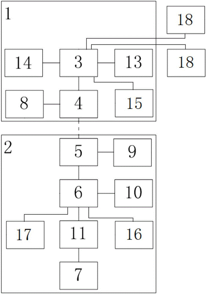
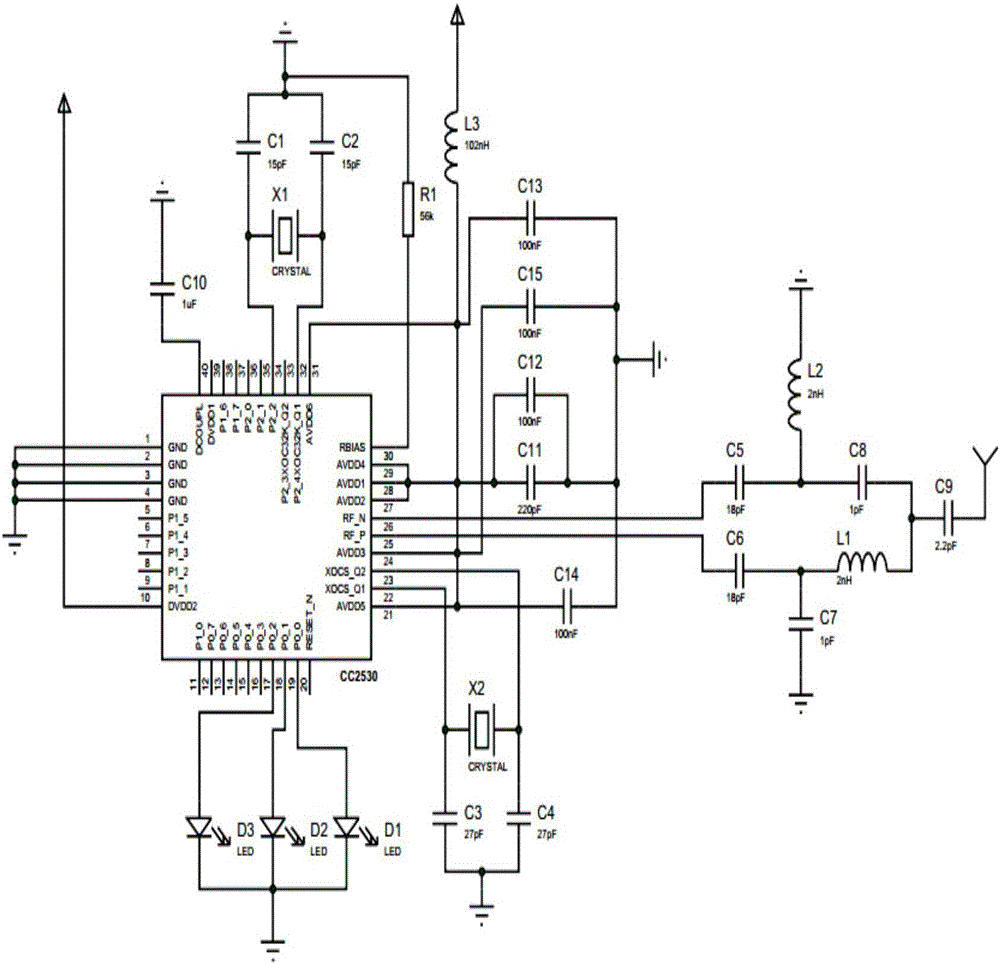
[0048] Embodiment 1 of the present invention: a remote-controllable mobile guardrail system, such as Figure 1 to Figure 6 As shown, it includes: a control device 1 and an execution terminal 2 located on the guardrail; the control device 1 is provided with a PC 3 and an A signal transceiver 4, and the PC 3 is connected to the A signal transceiver 4; The executive terminal 2 is provided with a B signal transceiver 5, a controller 6 and a motor 7, the controller 6 is connected with the B signal transceiver 5 and the motor 7, and the motor 7 drives the guardrail to move; the A signal The transceiver 4 is wirelessly connected with the B signal transceiver 5 . The A signal transceiver 4 is a zigbee controller, and the B signal transceiver 5 is a zigbee node. Described execution terminal 2 comprises a plurality of, and a plurality of execution terminals 2 are arranged on each mobile guardrail unit one by one respectively, and the B signal transceiver 5 on each mobile guardrail unit...
Embodiment 2
[0056] Embodiment 2: a remote-controllable mobile guardrail system, comprising: a control device 1 and an execution terminal 2 arranged on the guardrail; the control device 1 is provided with a PC 3 and an A signal transceiver 4, and the PC 3 is connected with A signal transceiver 4; Described executive terminal 2 is provided with B signal transceiver 5, controller 6 and motor 7, and described controller 6 is connected with B signal transceiver 5 and motor 7 respectively, and motor 7. Drive the guardrail to move; the A signal transceiver 4 is wirelessly connected to the B signal transceiver 5. The A signal transceiver 4 is a zigbee controller, and the B signal transceiver 5 is a zigbee node. Described execution terminal 2 comprises a plurality of, and a plurality of execution terminals 2 are arranged on each mobile guardrail unit one by one respectively, and the B signal transceiver 5 on each mobile guardrail unit all sends and receives the B signal on its adjacent mobile guar...
Embodiment 3
[0061] Embodiment 3: A remote-controllable mobile guardrail system, comprising: a control device 1 and an execution terminal 2 arranged on the guardrail; the control device 1 is provided with a PC 3 and an A signal transceiver 4, and the PC 3 is connected with A signal transceiver 4; Described executive terminal 2 is provided with B signal transceiver 5, controller 6 and motor 7, and described controller 6 is connected with B signal transceiver 5 and motor 7 respectively, and motor 7. Drive the guardrail to move; the A signal transceiver 4 is wirelessly connected to the B signal transceiver 5. The control device 1 also includes: a first LED state signal indicator 8, which is electrically connected to the A signal transceiver 4; the execution terminal 2 is also provided with a second LED state indicator light. The signal indicator light 9, the second LED state signal indicator light 9 is connected with the B signal transceiver 5.
[0062] A control method of a remote-controlla...
PUM
 Abstract
Description
Claims
Application Information
 - R&D
- Intellectual Property
- Life Sciences
- Materials
- Tech Scout
- Unparalleled Data Quality
- Higher Quality Content
- 60% Fewer Hallucinations
Browse by: Latest US Patents, China's latest patents, Technical Efficacy Thesaurus, Application Domain, Technology Topic, Popular Technical Reports.
© 2025 PatSnap. All rights reserved.Legal|Privacy policy|Modern Slavery Act Transparency Statement|Sitemap|About US| Contact US: help@patsnap.com


