
Alarm system for monitoring abnormal state of power transformer

A power transformer and abnormal state technology, applied in the field of power transmission, can solve problems such as roughness, ambiguity in the mapping relationship between coding combinations and fault types, and inability to cover fault types

Inactive Publication Date: 2016-09-28
曹新民
View PDF7 Cites 2 Cited by
  • Summary
  • Abstract
  • Description
  • Claims
  • Application Information

AI Technical Summary

Problems solved by technology

[0004] As one of the DGA technologies, the three-ratio method has played a certain role in engineering practice, but due to the limited ratio coding, the fault types are only divided into some classic types, which cannot cover all fault types in actual operation. There is ambiguity in the mapping relationship between types. A simple one-to-one mapping cannot fully and objectively reflect the complex coupling relationship between symptoms and faults. There are also some inaccuracies in gas content that may be caused by various factors. Thus forming a misjudgment of the type of failure
At the same time, the current three-ratio method is mainly to judge the type of fault. Since the judgment of the fault type is relatively rough, it does not reveal the fault location and the severity of the fault. Therefore, it is difficult for decision makers to determine a complete maintenance based on the diagnosis results of the three-ratio method. Strategy
[0005] Therefore, it is necessary to improve the current DGA technology to improve the accuracy and stability of diagnosing power transformer faults, and to avoid adverse effects caused by misjudgment operations.

Method used


Image

  • Alarm system for monitoring abnormal state of power transformer
  • Alarm system for monitoring abnormal state of power transformer
  • Alarm system for monitoring abnormal state of power transformer

Examples


Embodiment Construction

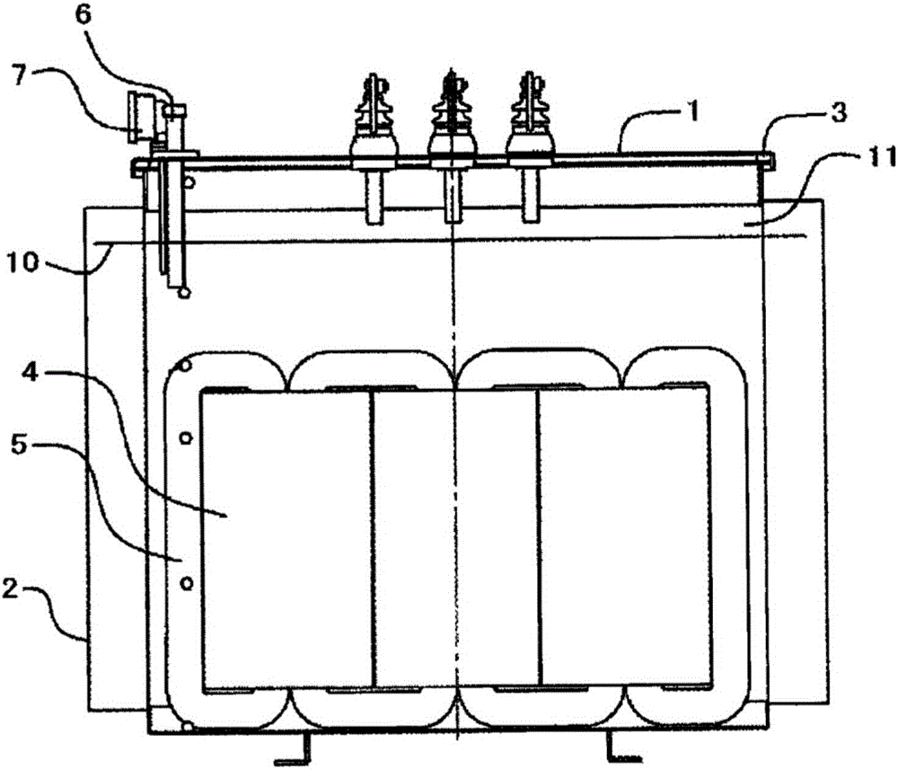
[0016] Such as figure 1 As shown, the structure diagram of the oil-immersed power transmission transformer of the present invention, the transformer includes a transformer housing 1 covering the entire transformer, an insulating oil tank 2 connected to the transformer housing 1, a transformer liner 3, and the main functional parts of the power transmission transformer The winding coil 4 and the iron core 5, the detection device 6 and the thermometer 7 are located at the upper edge of the transformer housing 1 for detection of relevant control data, and the insulating oil 10 and the air layer 11 in the insulating oil tank 2 are located. During the operation of the transformer, it will be affected by various factors such as mechanical stress, temperature, strong electric field, moisture, oxygen, etc. Under the action of these factors, the insulating oil will undergo various chemical reactions such as carbonization, cracking, and oxidation to generate hydrogen, Low molecular hydr...


PUM


Abstract

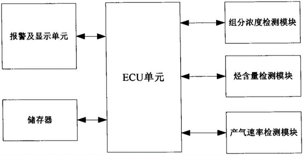
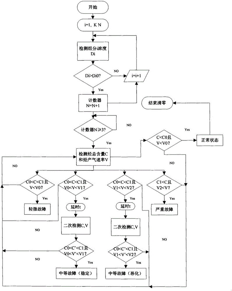
An alarm system for monitoring abnormal state of a power transformer comprises an ECU unit, a memory unit, three detecting modules and an alarm-and-display unit. The alarm system is characterized in that the three detecting modules comprise a component concentration detecting module, a hydrocarbon component detecting module and a gas production speed detecting module; wherein the component concentration detecting module, the hydrocarbon component detecting module and the gas production speed detecting module are connected with an ECU unit, receive control instruction of the ECU unit and perform feedback of related signals to the ECU unit; the memory unit is connected with the ECU unit; and the alarm-and-display unit displays an alarm signal which is output of the ECU unit to outside. According to the alarm system, a two-step determining process which comprises a primary concentration alarm operation and an alarm grading operation is utilized, thereby maximally preventing measurement inaccuracy or measurement instability caused by multiple factors, realizing accurate graded alarm and reminding an operator of corresponding maintenance, etc.

Description

technical field [0001] The invention relates to an alarm system for monitoring the abnormal state of a power transformer, which belongs to the technical field of power transmission. Background technique [0002] With the rapid development of my country's electric power industry, power transformers are developing in the direction of ultra-high voltage and large capacity, and the power grid is also being organized into a huge regional or even trans-regional power grid. A connected grid pattern is taking shape. With the increase of power equipment capacity and the expansion of power grid scale, higher requirements are put forward for the safe operation and power supply reliability of the power system. The transformer plays an important role in the power system and is one of the most important and expensive electrical equipment in the power system. The safety and reliability of its operation is directly related to the safety and stability of the power system. Therefore, improvi...

Claims


Application Information

Patent Timeline
Patent Type & Authority Applications(China)
IPC IPC(8): G08B21/18
CPCG01N33/0065G01R31/00G08B21/182G08B21/185H01F27/402
Inventor 不公告发明人
Owner 曹新民
Learn More