Magnetostatic method for online monitoring vibration marks of magneto-conductive continuous casting billet

A continuous casting slab and magnetic force technology, applied in the configuration of indicating equipment/measuring equipment, casting equipment, manufacturing tools, etc., can solve the problems of complex, limited and difficult ray equipment, and achieve simple detection equipment, simple measurement process, Detect fast effects

Active Publication Date: 2016-10-05
UNIVERSITY OF CHINESE ACADEMY OF SCIENCES +1
View PDF7 Cites 0 Cited by
  • Summary
  • Abstract
  • Description
  • Claims
  • Application Information

AI Technical Summary

Problems solved by technology

Optical inspection can judge the defects and distribution inside the object by detecting the intensity of transmitted rays. It has the characteristics of non-contact, pollution-free, fast and intuitive, but the ray equipment is complicated and expensive, and the quantitative evaluation of defects is difficult, and Due to the formation of a layer of oxide skin on the surface of the slab under strong water cooling conditions, the accuracy of optical measurement is further affected
The biggest advantage of eddy current testing technology is that it can detect surface and near-surface defects, but due to

Method used


Image

  • Magnetostatic method for online monitoring vibration marks of magneto-conductive continuous casting billet
  • Magnetostatic method for online monitoring vibration marks of magneto-conductive continuous casting billet
  • Magnetostatic method for online monitoring vibration marks of magneto-conductive continuous casting billet

Examples


Embodiment Construction

[0027] The technical solutions of the present invention will be described in further detail below with reference to the accompanying drawings and embodiments.

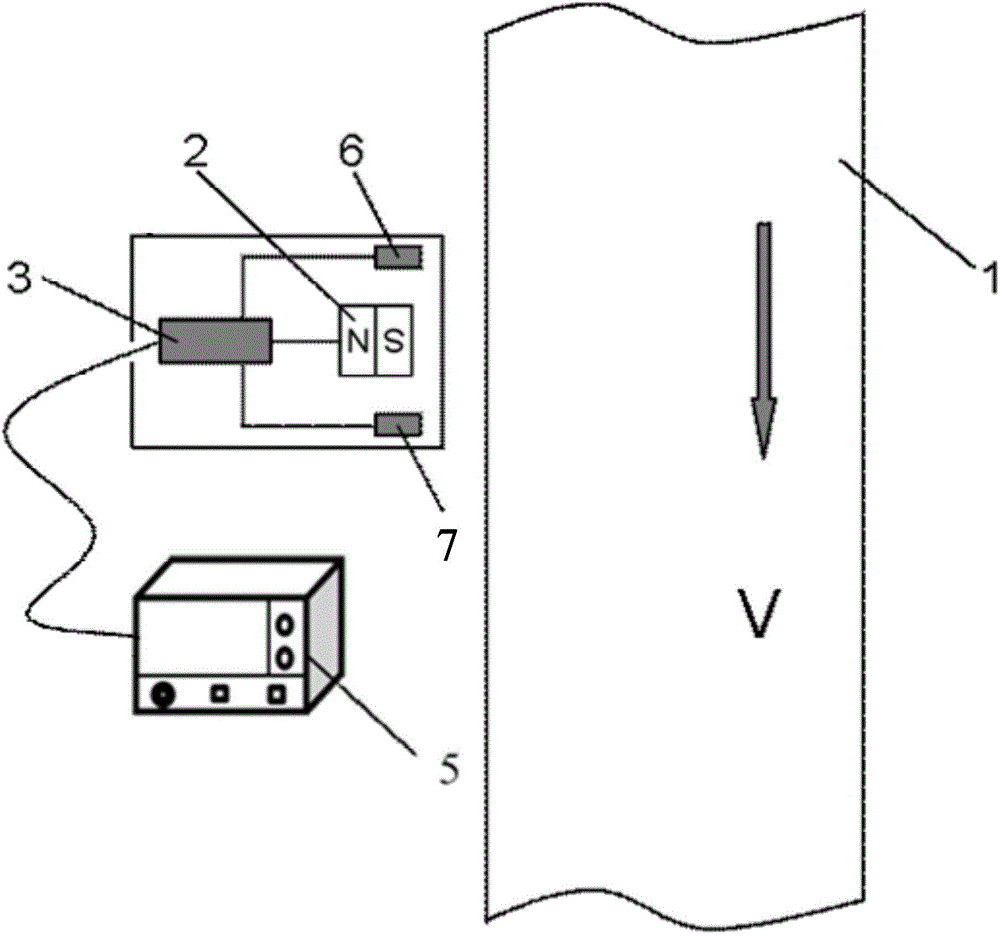
[0028] figure 1 It is a schematic diagram of the system used in the static magnetostatic method for on-line monitoring of vibration marks of magnetically conductive continuous casting slabs in the present invention, as shown in the figure, which includes a continuous casting slab 1 to be tested that has been pulled down after being water-cooled. Place the permanent magnet 2 on the surface of the continuous casting slab 1 to be tested, and the load cell 3 connected with the permanent magnet and the oscilloscope 5 connected on the load cell 3, and the thermocouple 6 and the thermocouple for measuring the surface temperature of the slab A distance measuring sensor 7 for measuring the distance between the permanent magnet and the surface of the slab.

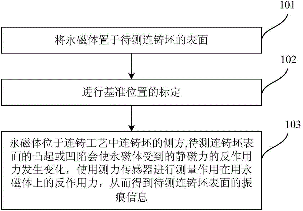
[0029] figure 2 It is a flow chart of the static magnetic force meth...


PUM


Abstract

The invention relates to a magnetostatic method for online monitoring vibration marks of a magneto-conductive continuous casting billet. The magnetostatic method comprises the following steps that a permanent magnet is arranged on the surface of a continuous casting billet in the continuous pulling down process, wherein the magnetization direction of the permanent magnet is perpendicular to the billet surface, to be detected, of the continuous casting billet to be detected; by utilizing calibration of a vibration mark-free continuous casting billet with the same material as the continuous casting billet to be detected, a force sensor is used to determine the counter-force F0' applied to the magnetostatic force F0 on a magnet; and the continuous casting billet, to be detected, with the vibration marks is determined and passes through the lower side of the permanent magnet, a bulge or a depression formed in the surface of the continuous casting billet to be detected can make the permanent magnet vary by subjecting to the counter-force F0' of the magnetostatic force, the force sensor which is connected with the end part of the permanent magnet is used to measure the counter-force F0' applied to the permanent magnet, and thus information of the vibration marks of the surface of the continuous casting billet to be detected is obtained. The magnetostatic method for online monitoring the vibration marks of the magneto-conductive continuous casting billet is simple and convenient, is accurate in result and can monitor variations of the vibration marks according to signal analysis on defects.

Description

technical field [0001] The invention relates to the technical field of metallurgical detection, in particular to a static magnetostatic force method for on-line monitoring of vibration marks of magnetically conductive continuous casting slabs. Background technique [0002] Continuous casting is a casting process in which molten steel is continuously passed through a water-cooled crystallizer, solidified into a shell, and then continuously pulled out from the outlet below the crystallizer, cooled by spraying water, and cut into billets after it is completely solidified. In order to prevent the slab from sticking to the mold wall during the solidification process, mold vibration technology is usually used in the continuous casting process, and mold slag is used for lubrication to make the continuous casting process go smoothly. Mold vibration is beneficial to the stripping of the continuous casting slab, but the vibration also causes vibration marks on the surface of the slab....

Claims


Application Information

Patent Timeline
IPC IPC(8): B22D2/00B22D11/115
Inventor 陈新悦王晓东任忠鸣
Owner UNIVERSITY OF CHINESE ACADEMY OF SCIENCES
Why Eureka
Try Eureka