Dual-power input speed reducer based on permanent magnet driving technique and power switching method of dual-power input speed reducer

A permanent magnet transmission and power input technology, which is applied in the direction of permanent magnet clutch/brake, transmission device, electric components, etc., can solve the problem of affecting the insulation and heat dissipation of the motor, the life of the motor, the safety of production and economic benefits, and the high speed of the air preheater motor. problems, to achieve the effect of prolonging the maintenance cycle and service life, eliminating vibration, and stabilizing the operation state of the equipment

Inactive Publication Date: 2016-10-05
MAGNA MAGNETOMOTIVE CO LTD
View PDF9 Cites 17 Cited by
  • Summary
  • Abstract
  • Description
  • Claims
  • Application Information

AI Technical Summary

Problems solved by technology

[0007] The main problems in the operation of this system are: 1) The starting torque of the reducer is large. Although the frequency converter is used as a soft start, the driving gear at the front end of the motor is easy to wear. When the gear is damaged, the motor needs to be removed for replacement. The main and backup motors jointly drive a reducer, and when the auxiliary motor A is started, the main motor A will rotate. During the operation of the motor, it is necessary to reduce the load and stop the air preheater for maintenance and elimination, which will seriously affect the safety of production and economic benefits.
2) The motor and the reducer are assembled in one piece, the front cover of the motor is soaked in lubricating oil, the motor speed of the air preheater is high, and the skeleton oil seal (55×70×8) is easy to leak oil during operation, so that the stator, The rotor is immersed in oil, which seriously affects the insulation, heat dissipation and life of the motor

Method used


Image

  • Dual-power input speed reducer based on permanent magnet driving technique and power switching method of dual-power input speed reducer
  • Dual-power input speed reducer based on permanent magnet driving technique and power switching method of dual-power input speed reducer
  • Dual-power input speed reducer based on permanent magnet driving technique and power switching method of dual-power input speed reducer

Examples


Embodiment Construction

[0031] The specific embodiment of the present invention will be further described below in conjunction with accompanying drawing:

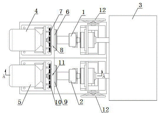
[0032] See figure 1 , is a structural schematic diagram of the first embodiment of the dual power input reducer based on permanent magnet transmission technology in the present invention, including the first power input assembly 1, the second power input assembly 2 and the gear transmission mechanism 3, the first power input assembly 1 and the second The power input assembly 2 cooperates with the power input end of the gear transmission mechanism 3 in a manner that can be engaged or disconnected respectively; The power output end of the first power input assembly 2 is in transmission cooperation with the power input end of the second power input assembly 2, and the first power input assembly 1 makes the power output end of the first motor 4 engage with the power input end of the gear transmission mechanism 3 for transmission or To form a disconnect...


PUM


Abstract

The invention relates to the field of speed reducers and particularly relates to a dual-power input speed reducer based on a permanent magnet driving technique and a power switching method of the dual-power input speed reducer. The dual-power input speed reducer is characterized in that a power input end I is connected with a first motor through a first power input assembly on a speed driving speed reduction mechanism with two power input ends, and a power input end II is connected with a second motor through a second power input assembly; the structures of the first power input assembly and the second power input assembly are designed on the basis of the permanent magnet driving technique, conductor discs and permanent magnet discs are arranged in the first power input assembly and the second power input assembly, and magnetic bodies on the permanent magnet discs are distributed at N-S intervals; and when the conductor discs rotate, the magnetic torque is generated, the air gaps between the conductor discs and the permanent magnet discs are adjusted through an adjustment mechanism, and therefore, the switch-on and the switch-off between the motors and a gear driving mechanism are finished. Compared with the prior art, the dual-power input speed reducer has the beneficial effects that the hard connection between a load and the motors is isolated, the buffer starting of the load can be realized, and the overhauling and the correction of the motors in a working state can be realized.

Description

technical field [0001] The invention relates to the field of reducers, in particular to a double power input reducer based on permanent magnet transmission technology and a power switching method thereof. Background technique [0002] At present, due to the characteristics of double input, the double power input reducer has been applied in various occasions of mechanical equipment. Its structure includes cylindrical gear reducer, worm reducer, planetary gear reducer and other forms, among which cylindrical gear reducer The dual power of the reducer adopts the same speed and torque, while the double power of the worm reducer and the planetary gear reducer can have different speed and torque. [0003] The simplest double-input structure in the cylindrical gear reducer is that the input shaft is one shaft, and the shaft protrudes from both sides of the reducer. Due to structural space constraints, sometimes there is no extra space on one input shaft to arrange the motor, coupl...

Claims


Application Information

Patent Timeline
Patent Type & Authority Applications(China)
IPC IPC(8): F16H49/00H02K49/10H02K7/116
Inventor 马忠威陈明东
Owner MAGNA MAGNETOMOTIVE CO LTD
Why Eureka
Try Eureka