Supercharge Your Innovation With Domain-Expert AI Agents!

Metal plate UV roller coating drying system

A drying system and metal plate technology, applied in coatings, devices for applying liquid to surfaces, paint spray booths, etc., can solve problems such as inability to treat exhaust gas, environmental pollution, etc., to remove harmful gases, prevent environmental pollution, and improve work. The effect of efficiency

Inactive Publication Date: 2016-10-12
YIXING FUSHENG MACHINERY
View PDF8 Cites 4 Cited by
  • Summary
  • Abstract
  • Description
  • Claims
  • Application Information

AI Technical Summary

Problems solved by technology

It has changed the traditional drying form, but its production will generate a large amount of tail gas, which cannot be treated, causing serious environmental pollution and needs to be improved

Method used


Image

  • Metal plate UV roller coating drying system

Examples


Embodiment 1

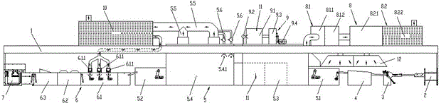
[0011] Embodiment 1: A metal plate UV roller coating drying system, comprising a long direction sealed housing 1, inside the housing 1 are arranged sequentially connected feeder 2, coating machine 3, conveying section 4, Drying room 5, UV light curing device 6 and blanking machine 7, drying room 5 includes feed section 5.1 and discharge section 5.2 at both ends, drying room heating chamber 5.3, drying room cooling chamber 5.4, UV light curing device 6 includes light Solid section 6.1, cooling section 6.2, and sample-seeing delivery section 6.3. Two conical smoke collection hoods 12 are arranged side by side above the delivery section 4. The smoke collection hoods 12 are connected to the waste gas treatment device 8 arranged on the top of the housing 1 through pipelines. The exhaust gas treatment device 8 includes a gas collection chamber 8.1 and a filter chamber 8.2 connected to the gas collection chamber 8.1. An intermediate partition is arranged in the gas collection chamber ...


PUM


Abstract

A metal plate UV roller coating drying system comprises a long sealed shell. A feed machine, a coating machine, a conveying section, a drying room, a UV photocuring device and a discharging machine are sequentially connected inside the shell from left to right. The drying room comprises a feed section, a discharge section, a drying room heating chamber and a drying room cooling chamber, wherein the feed section and the discharge section are arranged at the two ends of the drying room. The UV photocuring device comprises a photocuring section, a cooling section and a convey-by-sample section. A plurality of conical exhaust fume collecting hoods are parallelly arranged above the conveying section and connected with a waste gas treatment device arranged at the top end of the shell through pipelines. The waste gas treatment device comprises a gas collecting chamber and a filtering chamber connected with the gas collecting chamber through a pipeline. An intermediate partition is arranged in the gas collecting chamber to partition the gas collecting chamber into a recovery compartment and a settling compartment. The filtering chamber comprises an electrolytic separation compartment and an adsorption filtering compartment. An exhaust duct is arranged at the top end of the adsorption filtering compartment. A heating device is arranged at the top end of the drying room heating chamber and comprises a heating bin and a burner, wherein the heating bin communicates with the drying room heating chamber, and the burner is arranged on the right side of the heating bin and connected with the heating bin through a pipeline.

Description

technical field [0001] The invention relates to the field of UV roll coating and drying of metal sheets. Background technique [0002] In the traditional iron printing and aluminum industry, there are drying rooms for coating, printing, and glazing drying of metal plates. The length of the drying room is about 40 meters, and the height is about 4.8 meters. It uses coal-fired boilers, natural gas, and oil combustion for heating and baking, which produces a large amount of greenhouse gases and Organic gas, polluting the environment. The traditional drying room uses a chain flower iron frame structure, each flower iron frame weighs about 2000g, the flower iron frame does not need to be heated, but in actual use, the flower iron frame is placed with the metal plate, one plate and one flower iron frame Being periodically heated and then cooled, the energy waste is serious. Add waste gas treatment and environmental protection equipment, the project investment is large, and the o...

Claims


Application Information

Patent Timeline
IPC IPC(8): B05D3/04B05D3/06B05B15/12
CPCB05B16/20B05D3/0413B05D3/067
Inventor 冯富胜董明喜张鑫
Owner YIXING FUSHENG MACHINERY
Features
  • R&D
  • Intellectual Property
  • Life Sciences
  • Materials
  • Tech Scout
  • Unparalleled Data Quality
  • Higher Quality Content
  • 60% Fewer Hallucinations
Learn More