Spiral stirrup continuously and synchronously machining machine and machining method

A spiral stirrup and synchronous processing technology, applied to wire processing, other household appliances, household appliances, etc., can solve the problems of small binding force and cannot effectively adapt to the building requirements of seismic strength, etc., to achieve convenient processing, production, installation and layout, and structural Simple, well-designed effects

Inactive Publication Date: 2016-10-12
刘国政 +1
View PDF9 Cites 26 Cited by
  • Summary
  • Abstract
  • Description
  • Claims
  • Application Information

AI Technical Summary

Problems solved by technology

In the event of a major earthquake, the restraining force is too sma

Method used


Image

  • Spiral stirrup continuously and synchronously machining machine and machining method
  • Spiral stirrup continuously and synchronously machining machine and machining method
  • Spiral stirrup continuously and synchronously machining machine and machining method

Examples


Embodiment 1

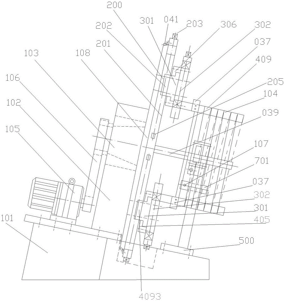
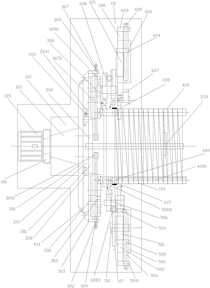
[0117] Such as figure 1 , figure 2 , image 3 and Figure 12 As shown, the present invention includes a fuselage base 101, a spiral stirrup processing device installed on the fuselage base 101 and gradually inclined downward from the rear to the front, and a monitoring device for monitoring the spiral stirrup processing device; by setting The spiral stirrup processing device is gradually inclined downward from the back to the front, so that the processed spiral stirrup can be slid and unloaded from the spiral stirrup processing device under the action of gravity, which not only reduces the manual labor, but also Production costs are reduced. The winding number and winding speed of the spiral stirrup can be monitored in real time by setting the monitoring device, so that the processing process of the spiral stirrup is easy to control and convenient to realize.

[0118] The spiral stirrup processing device includes a rotary table 200 installed on the fuselage base 101, a st...

Embodiment 2

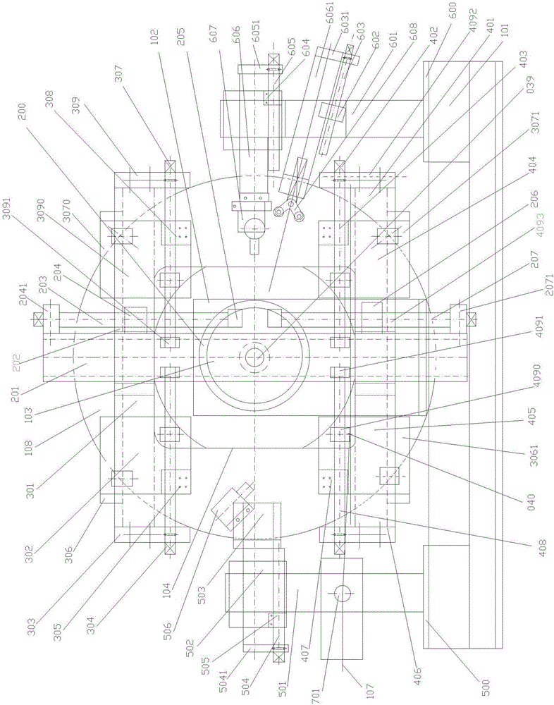
[0221] In this example, if Figure 14 As shown, the difference between the spiral stirrup continuous synchronous processing machine and the processing method used in Embodiment 1 is that the number of the winding shafts 409 is eight. The eight winding shafts 409 are respectively the first upper left winding shaft, the second upper left winding shaft, the first right upper winding shaft, the second right upper winding shaft, the first left lower winding shaft, the Two lower left winding shafts, a first lower right winding shaft and a second lower right winding shaft.

[0222] In this way, by changing the number of winding shafts 409 and changing the processing shape of the spiral stirrup 104, polygonal spiral stirrups can be processed according to requirements, which improves the flexibility of the continuous synchronous processing machine for spiral stirrups and has a wide range of applications.

[0223] In this embodiment, the rest of the structure, connection relationship a...


PUM


Abstract

The invention discloses a spiral stirrup continuously and synchronously machining machine and a machining method. The machining machine comprises a machine body seat, a spiral stirrup machining device and a monitoring device. The spiral stirrup machining device comprises a rotary workbench, a stirrup winding mechanism, a feeding mechanism and a cutting mechanism. The stirrup winding mechanism comprises a stirrup twining frame, a rolling type bending mechanism and a screw pitch axial feed mechanism. The monitoring device comprises a control device, a counting unit and a rotating speed measuring unit. The machining method comprises the first step of determining the number of winding shafts and the installation position, the second step of adjusting the positions of the winding shafts, the third step of feeding and positioning stirrup material, the fourth step of forming spiral stirrups and the fifth step of cutting spiral stirrups. The machining machine is simple in structure, continuous machining of spiral stirrups is achieved, and the production efficiency is high; meanwhile, the concrete constraining force of beam columns of buildings can be improved through the produced spiral stirrups, and therefore the seismic capacity of the buildings is improved. Practicality is high, and the machining machine and the machining method are low in carbon, environmentally friendly and efficient and save energy.

Description

technical field [0001] The invention belongs to the technical field of processing spiral stirrups for construction, and in particular relates to a continuous and synchronous processing machine for spiral stirrups and a processing method. Background technique [0002] With the continuous improvement of the structural strength requirements of various buildings, especially after many strong earthquakes at home and abroad, the high seismic strength requirements of buildings have attracted great attention from the construction industry, and most of the actual buildings Is the use of a single form or way stirrup concrete molding. In the event of a major earthquake, the restraining force is too small and cannot effectively meet the building requirements for seismic strength. Buildings generally have a short lifespan, and people hope that buildings with long lifespan, strong earthquake resistance, low-carbon environmental protection, and energy-saving and green buildings will be re...

Claims


Application Information

Patent Timeline
IPC IPC(8): B21F3/04B21F23/00B21F11/00B21F45/00
CPCB21F3/04B21F11/00B21F23/00B21F45/006
Inventor 戴军刘国政乔洪生王亚新
Owner 刘国政
Why Eureka
Try Eureka