Intelligent laser 3D printing device and method
A 3D printing and laser technology, applied in the direction of improving energy efficiency, process efficiency, additive processing, etc., can solve problems such as parts deformation and cracking, internal defects, internal organization, etc., to improve quality, reduce operating costs, and improve intelligence effect
- Summary
- Abstract
- Description
- Claims
- Application Information
AI Technical Summary
Problems solved by technology
Method used
Image

Examples
Embodiment Construction
[0031] The present invention will be further described in detail with reference to the accompanying drawings and embodiments.
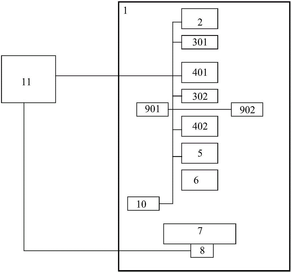
[0032] The present invention proposes an intelligent laser 3D printing device and printing method, such as figure 1 As shown, the printing device includes a housing 1, a semiconductor laser 2, a vibrating mirror X301, a vibrating mirror Y302, a scanning mirror X401, a scanning mirror Y402, a field mirror 5, a melting pool 6, a workpiece table 7, a drive motor 8, CCDA901, CCDB902, laser heterodyne interferometer 10 and computer 11. The workpiece table 7 and the drive motor 8 form a six-axis parallel load system, and the drive motor 8 drives the workpiece table 7 to move, so as to realize the azimuth movement control of the physical objects on the workpiece table 7 . Described semiconductor laser device 2, vibrating mirror X301, vibrating mirror Y302, scanning mirror X401, scanning mirror Y402, field mirror 5, melting pool 6, work table 7, drive motor ...
PUM
| Property | Measurement | Unit |
|---|---|---|
| Diameter | aaaaa | aaaaa |
Abstract
Description
Claims
Application Information
PatSnap Eureka turns technology decisions into work you can execute. Powered by our Innovation Knowledge Graph, it runs expert workflows across engineering, life sciences, materials and intellectual property. Get your review-ready output in minutes.


