Boiler fully utilizing smoke gas waste heat

A flue gas waste heat and boiler technology, applied in the direction of air heaters, preheating, water heaters, etc., can solve the problems of low heat transfer efficiency, poor heat transfer effect, damage, etc., and achieve heat saving, effective heat energy, and work efficiency Enhanced effect

Inactive Publication Date: 2016-10-12
HARBIN JINJING BOILER
View PDF0 Cites 11 Cited by
  • Summary
  • Abstract
  • Description
  • Claims
  • Application Information

AI Technical Summary

Problems solved by technology

[0004]At present, the energy-saving heat exchange devices on the market generally hav

Method used


Image

  • Boiler fully utilizing smoke gas waste heat

Examples


Embodiment 1

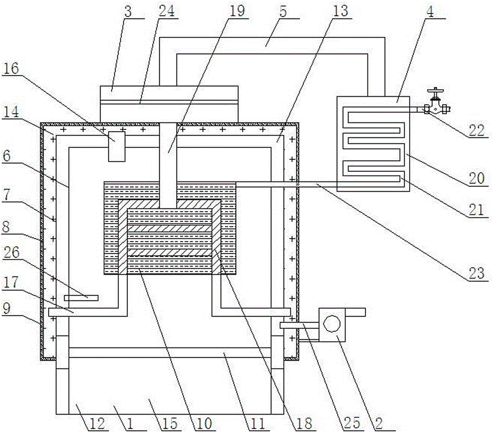
[0020] Such as figure 1 As shown, a boiler that makes full use of the waste heat of flue gas includes a furnace body 1, a blast device 2, a flue gas chamber 3, and a preheating water tank 4. Chamber 3, the flue gas chamber 3 is connected to the preheating water tank 4 through the gas delivery pipe 5; the interior of the furnace body 1 is composed of an inner shell 6, a middle shell 7, an outer shell 8, and a thermal insulation shell 9; The interior of the shell 6 is a combustion chamber 15, which is installed in the center of the furnace body 1. The internal device is a heating water tank 10, a fire grate 11, and an ash chamber 12. The fire grate 11 is installed at the lower end of the inner shell 6. The fire grate The lower end of 11 is the ash chamber 12, and the heating water tank 10 is installed at the upper end of the inner shell 6; the air preheating chamber 13 is formed between the middle shell 7 and the inner shell 6; the outer shell 8 and the middle shell A flue g...

Embodiment 2

[0022] Such as figure 1 As shown, the left side of the top of the combustion chamber 15 is connected to the flue gas circulation chamber 14 through the first smoke exhaust pipe 16, and the left lower end and the right lower end of the flue gas circulation chamber 14 are respectively connected to the combustion chamber 15 through a flue gas delivery pipe 17. The internal heating water tank 10 is equipped with a heat exchange device 18 inside the heating water tank 10. The lower end of the heat exchange device 18 is connected to two flue gas delivery pipes 17, and the upper end is equipped with a second smoke exhaust pipe 19. The second smoke exhaust pipe 19 The upper end is connected with the flue gas chamber 3 .

Embodiment 3

[0024] Such as figure 1 As shown, the blower device 2 is connected to the right lower end of the air preheating chamber 13 through the cold air delivery pipe 25 , and the left lower end of the air preheating chamber 13 is connected to the combustion chamber 15 through the preheating air delivery pipe 26 .


PUM


Abstract

A boiler fully utilizing smoke gas waste heat comprises a boiler body, an air blower, a smoke gas chamber and a preheating water tank, wherein the air blower is arranged at the right lower end of the boiler body, the smoke gas chamber is arranged at the top end of the boiler body, and the smoke gas chamber is connected with the preheating water tank through a gas delivery pipe; an inner shell, a middle shell, an outer shell and a thermal insulating and heat preserving shell are formed in the boiler body; the inner part of the inner shell is a combustion chamber, the inner shell is arranged in the center in the boiler body, a heating water tank, a grate and an ash chamber are arranged in the inner shell, the grate is arranged at the lower end in the inner shell, the lower end of the grate is the ash chamber, and the heating water tank is arranged at the upper end in the inner shell; an air preheating chamber is formed between the middle shell and the inner shell; a smoke circulating chamber is formed between the outer shell and the middle shell; and the thermal insulating and heat preserving shell is arranged at the outer end of the outer shell. The boiler can fully utilize waste heat in smoke gas to preheat to-be-heated water and preheat combustion air which will enter the combustion chamber, so that heat energy is saved, and thermal pollution is reduced.

Description

technical field [0001] The invention relates to the field of boiler equipment, in particular to a boiler that fully utilizes the waste heat of flue gas. Background technique [0002] In today's society, energy saving has become the "fifth energy source" after coal, electricity, oil and natural gas. However, in the use of current boilers, there are generally problems such as low heat utilization rate and excessively high exhaust gas waste heat temperature. [0003] In the past ten years, due to energy shortage, with the further development of energy conservation work. Various new, energy-saving and advanced boilers are becoming more and more perfect. The advanced combustion device is used to strengthen the combustion and reduce the amount of incomplete combustion. However, technologies to reduce exhaust heat loss and recover flue gas waste heat are still progressing slowly. In order to further improve the thermal efficiency of the boiler and achieve the purpose of saving ...

Claims


Application Information

Patent Timeline
IPC IPC(8): F24H1/34F22D1/00F28D1/047F23J15/02F24H3/08
CPCF24H1/34F22D1/003F22D1/006F23J15/025F24H3/08F28D1/047
Inventor 谷哲学
Owner HARBIN JINJING BOILER
Why Eureka
Try Eureka