
Sunshine introducing device with automatic sunshine tracking

An automatic tracking and introduction device technology, applied in the field of solar energy applications, can solve the problems of affecting the transmission distance, the influence of the house structure, and the large volume of sunlight importing equipment, and achieve the effect of low transmission loss rate and excellent installation convenience

Active Publication Date: 2016-10-12
倪屹
View PDF9 Cites 7 Cited by
  • Summary
  • Abstract
  • Description
  • Claims
  • Application Information

AI Technical Summary

Problems solved by technology

[0005] The light attenuation rate of the light-guiding fiber is quite different for different bands, and the currently commonly used silica fiber has a large attenuation for ultraviolet and infrared rays.
At the same time, the diameter of the optical fiber is very small, and usually many optical fibers need to be spliced ​​together for use, which leads to a very high cost of the optical fiber transmission solution. Although the sunlight converging scheme is adopted, only a small part of the concentrated sunlight can enter the optical fiber transmission
Although the light guide tube is used for full-band transmission, the light guide tube also faces different directions after the light converges, and the movement and placement are more complicated. The loss at the corner is large, which affects the transmission distance. Some large-caliber light guides The diameter of the pipe is tens of centimeters, and the installation will have a great impact on the structure of the house
For example, the sunlight importing device disclosed in the document with the publication number CN104832877A still has the disadvantages of large volume, multiple reflections during the sunlight collection process resulting in excessive energy loss, inability to track the incoming sunlight, and cluttered collection of light rays that are difficult to collect.

Method used


Image

  • Sunshine introducing device with automatic sunshine tracking
  • Sunshine introducing device with automatic sunshine tracking
  • Sunshine introducing device with automatic sunshine tracking

Examples


Embodiment Construction

[0025] The present invention will be further described below in conjunction with specific drawings and embodiments.

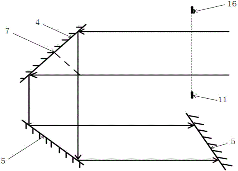
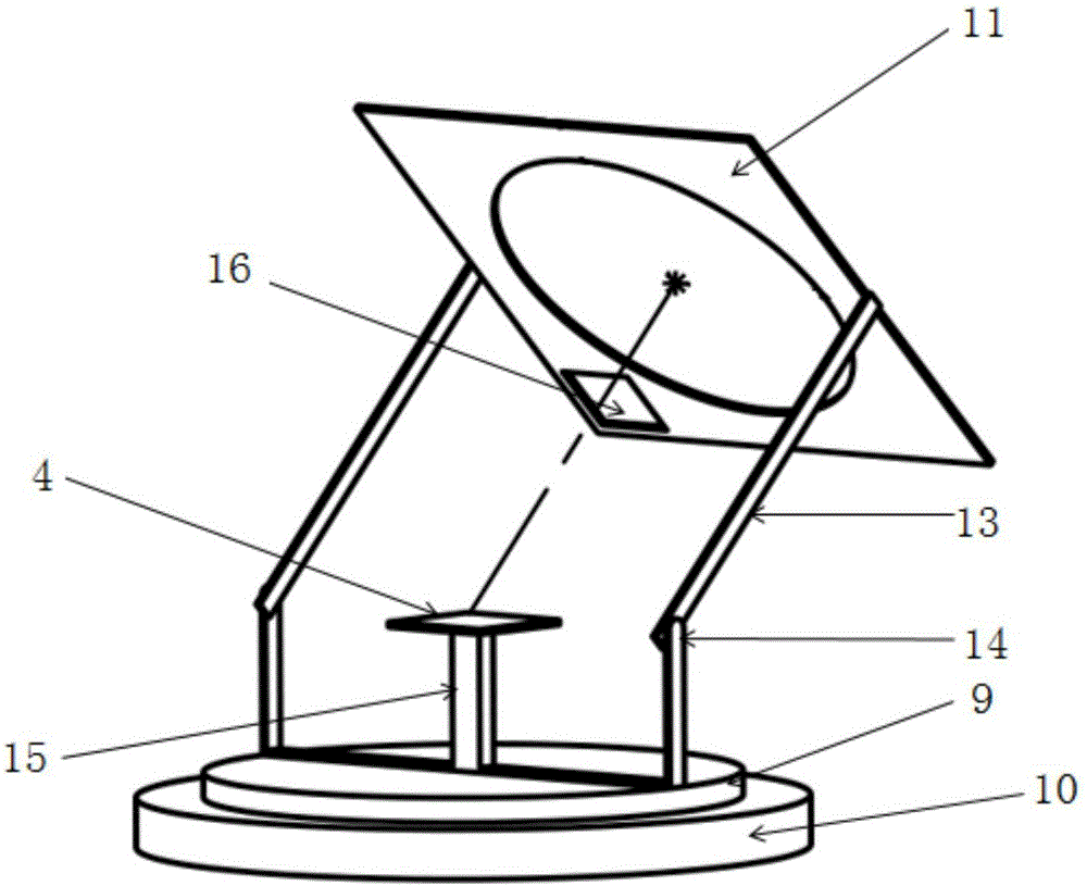
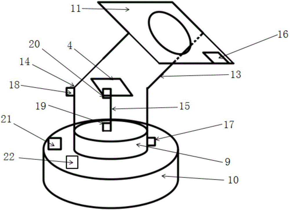
[0026] Such as figure 1 and Figure 4 Shown: In order to track the incident angle of sunlight, collect sunlight in a vertical direction, improve the collection rate of sunlight, and transmit the collected sunlight to the target position in the form of parallel light with a flat mirror group to reduce costs, the present invention includes A photometric panel 16 for receiving incident sunlight, an outer panel 11 for supporting the photometric panel 16, and a movable light-guiding plane mirror 4 for receiving the light passing through the outer panel 11, and the movable light-guiding plane mirror 4 A fixed light-guiding plane mirror group for transmitting sunlight to a desired position is arranged on the guiding light line; the photometric panel 16 is electrically connected to the sunlight tracking device, and the sunlight tracking device can be adjusted accordin...


PUM


Abstract

The invention relates to a sunshine introducing device with automatic sunshine tracking. The device comprises a light measuring panel, an outer-layer panel, and a movable light guide plane mirror for receiving sunshine passing through the outer-layer panel; a light guide path of the movable light guide plane mirror is provided with a fixed light guide plane mirror set for transmitting the sunshine to a needed position; the light measuring panel is electrically connected with a sunshine tracking device; and the sunshine tracking device can adjust the position of the outer-layer panel and the receiving state of the movable light guide plane mirror according to the irradiating state of the incident sunshine detected by the light measuring panel, so that the incident sunshine vertically irradiates the outer-layer panel, and the reflecting ray of the movable light guide plane mirror to the fixed light guide plane mirror set is kept constant. The device is compact in structure, can track the sunshine incident angle, can keep collection of the sunshine in the vertical incident direction, improves the sunshine collecting rate, transmits the collected sunshine to the target position by the plane mirror set in a parallel light form, and is low in cost, safe and reliable.

Description

technical field [0001] The invention relates to an introduction device, in particular to a sunlight introduction device equipped with automatic sunlight tracking, and belongs to the technical field of solar energy applications. Background technique [0002] In recent years, with people's emphasis on the environment, green energy has become the focus of the energy industry. Among green energy sources, solar energy is inexhaustible, clean and safe, and is the most ideal renewable energy source. The development of solar energy is highly valued internationally. As a new type of lighting system, the sunlight introduction system is becoming more and more popular, and it greatly saves energy. In basements, subways, shopping malls, and inside some office buildings, electric lighting is required even during the day due to lack of light. According to statistics, the electricity consumed by lighting in the daytime in the area now accounts for more than 20% of the electricity required...

Claims


Application Information

Patent Timeline
IPC IPC(8): F24J2/38F24J2/20F24J2/08F24J2/54H02S20/32F24J2/10F24S10/50F24S23/30F24S23/70F24S50/20
CPCF24S10/50F24S23/30F24S23/70F24S30/45F24S50/20F24S2030/11H02S20/32Y02E10/44Y02E10/47Y02E10/50
Inventor 倪屹
Owner 倪屹
Learn More