
Pre-drying system utilizing waste heat of textile drier

A dryer and pre-drying technology, applied in the direction of dryers, drying, heating devices, etc., can solve the problems of heat radiation pollution of high-temperature waste hot air flow, high energy consumption of textile dryers, and environmental impacts, etc., to achieve Improve the efficiency of drying treatment, reduce drying time, and reduce the effect of heat radiation

Inactive Publication Date: 2016-10-12
WUXI ANG YIDA MACHINERY
View PDF4 Cites 1 Cited by
  • Summary
  • Abstract
  • Description
  • Claims
  • Application Information

AI Technical Summary

Problems solved by technology

[0002] In the textile industry, the dryer is mainly used for drying and fixing the color of textile fabrics. The heating and drying methods mainly include hot air heating and electric heating. During the working process, the fabric in the dryer is After drying, the water evaporates to the inner space of the dryer, and is discharged out of the dryer with the hot air flow or the dehumidified air flow. The temperature of the discharged exhaust gas is relatively high, but because the exhaust gas is mixed with a large amount of impurities such as water vapor and fluff, It is not easy to reuse it, so usually the waste hot air will be directly discharged into the atmosphere, and the lost heat will cause a lot of waste of energy. Because the heat energy has not been effectively used, the textile dryer will It consumes a lot of energy, and the high-temperature waste hot air will bring serious thermal radiation pollution, which will have a great impact on the surrounding environment

Method used


Image

  • Pre-drying system utilizing waste heat of textile drier

Examples


Embodiment Construction

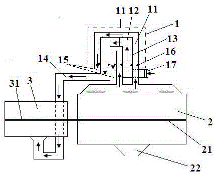
[0016] The present invention will be further described below in conjunction with the accompanying drawings. Such as figure 1 A pre-drying system using the waste heat of a textile dryer as shown includes a cloth pre-dryer 3 and a heat exchange device 1. The heat exchange device 1 is placed on the top of the cloth dryer 2 and includes a wet and hot exhaust gas channel 11 and The fresh dry air channel 12 is used to pump the hot and humid exhaust air and dry cold air discharged from the cloth dryer 2 respectively. A heat exchange device 13 is arranged between the hot and humid exhaust air channel 11 and the fresh dry air channel 12. The fresh dry air channel 12 The dry cold air circulating in the interior absorbs the heat of the hot and humid waste gas flowing through the hot and humid waste gas channel 11 by using the principle of heat exchange, and is discharged into the cloth pre-dryer 3 through the ventilation pipe 14 to pre-dry the cloth 31, and the cloth is pre-dried The ma...


PUM


Abstract

The invention discloses a pre-drying system utilizing waste heat of a textile drier. The pre-drying system comprises a cloth pre-drier and a heat exchange device, wherein the heat exchange device is arranged on the top of a cloth drier, and comprises a damp hot waste gas passage and a fresh dry air passage which are separately used for pumping in damp hot waste gas and dry cold air which are emitted by the cloth drier; a heat transfer device is arranged between the damp hot waste gas passage and the fresh dry air passage; dry cold air flowing in the fresh dry air passage absorbs heat of damp hot waste gas flowing by the damp hot waste gas passage by utilizing a heat exchange principle, and then is emitted into the cloth pre-drier through a vent pipe for pre-drying cloth; and the cloth pre-drier is located on the inlet side of the cloth drier, and is used for rolling the pre-dried cloth into the cloth drier for drying. According to the drier waste heat reutilization device provided by the invention, heat energy in the waste gas emitted by the textile drier is fully utilized, and the textile cloth is pre-dried, so that effective recycle for the waste heat is realized; energy is saved; and the environment is protected.

Description

technical field [0001] The invention relates to the technical field of heat energy recovery and utilization, in particular to a system for reusing waste heat after drying cloth by a textile cloth dryer. Background technique [0002] In the textile industry, the dryer is mainly used for drying and fixing the color of textile fabrics. The heating and drying methods mainly include hot air heating and electric heating. During the working process, the fabric in the dryer is After drying, the water evaporates to the inner space of the dryer, and is discharged out of the dryer with the hot air flow or the dehumidified air flow. The temperature of the discharged exhaust gas is relatively high, but because the exhaust gas is mixed with a large amount of impurities such as water vapor and fluff, It is not easy to reuse it, so usually the waste hot air will be directly discharged into the atmosphere, and the lost heat will cause a lot of waste of energy. Because the heat energy has not...

Claims


Application Information

Patent Timeline
Patent Type & Authority Applications(China)
IPC IPC(8): F26B23/10F28D7/00F24H3/00
CPCF24H3/00F26B23/10F28D7/00Y02P70/10
Inventor 吴震
Owner WUXI ANG YIDA MACHINERY
Learn More