
Vacuum heat collector

A heat collector and heat collecting tube technology, applied in the field of solar energy, can solve the problems of complex structure of heat collecting tube, high manufacturing and installation costs, complicated manufacturing process, etc. Effect

Pending Publication Date: 2016-10-19
YIKEBO ENERGY TECH SHANGHAI
View PDF11 Cites 5 Cited by
  • Summary
  • Abstract
  • Description
  • Claims
  • Application Information

AI Technical Summary

Problems solved by technology

Usually, the heat collecting tube adopts U-shaped thin tubes, and the surface of these U-shaped thin tubes is mostly coated with selective absorption coating, the manufacturing process is complicated, and multiple U-shaped thin tubes are connected in parallel in order to obtain a large heat absorption area. The method makes the structure of the heat collecting tube complicated, and the production and installation costs are relatively high

Method used


Image

  • Vacuum heat collector
  • Vacuum heat collector

Examples


Embodiment Construction

[0028] Preferred embodiments of the present invention will be described in detail below with reference to the accompanying drawings, so as to better understand the purpose, features and advantages of the present invention. It should be understood that the embodiments shown in the drawings are not intended to limit the scope of the present invention, but only to illustrate the essence of the technical solutions of the present invention.

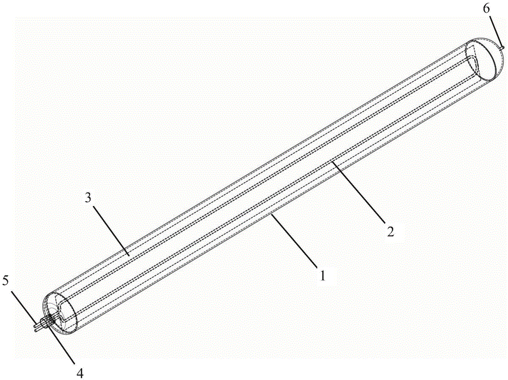
[0029] Such as figure 1 and 2 As shown, the heat collector of the present invention includes a housing 1, a U-shaped heat collecting tube 2, a heat absorbing plate 3 and a front end cover 4, wherein the housing includes a light-facing surface and a backlight surface, and the housing is provided with a vacuum nozzle 6 ; The U-shaped heat collecting tube 2 is fixedly installed in the housing, and the inlet and outlet ends of the U-shaped heat collecting tube 2 are connected with the sealing sleeve 5, and the sealing sleeve passes through the fr...


PUM


Abstract

The invention discloses a vacuum heat collector comprising a housing, a U-shape heat collecting tube, and a heat absorbing plate; the housing comprises a facing-light surface and a back-light surface and is provided with a vacuum suction nozzle; the U-shape heat collecting tube is fixedly installed inside the housing; the heat absorbing plate is installed between the facing-light surface of the housing and the U-shape heat collecting tube; the side, facing the facing-light surface of the housing of the heat absorbing plate is coated with selective absorbing coating, the other side of the heat absorbing plate is tightly fitted to the U-shape heat collecting tube; an enclosed vacuum environment can be formed inside the housing; sunshine irradiates on the heat absorbing plate through the facing-light surface of the housing and the heat absorbed by the heat absorbing plate can be used for heating heat transferring medium inside the U-shape heat collecting tube. The heat collector is provided with a heat absorbing plate which is coated with selective absorbing coating having high solar absorption efficiency and low reflection efficiency; the surface area of the heat absorbing plate is large and the heat absorbed by the heat absorbing plate can be quickly transferred to the U-shape heat collecting tube; a heat radiation shielding layer is used for reducing the heat radiation loss of the heat collector.

Description

technical field [0001] The invention relates to the technical field of solar energy, in particular to a U-shaped vacuum heat collecting tube. Background technique [0002] In the heat utilization of solar energy, the key is to convert the sun's radiant energy into heat energy. Since solar energy is scattered, it must be concentrated. A solar collector is a device used to absorb solar radiation to convert it into heat energy and transfer it to a heat medium. Although it is not a terminal product directly oriented to consumers, a solar collector is a key component of various solar heat utilization systems . Whether it is solar water heaters, solar cookers, active solar houses, solar greenhouses or solar drying, solar industrial heating, solar thermal power generation, etc., solar collectors are inseparable, and solar collectors are used as the power or core components of the system. of. The common ones are flat-plate, vacuum tube and concentrating solar collectors. [000...

Claims


Application Information

Patent Timeline
Patent Type & Authority Applications(China)
IPC IPC(8): F24J2/05F24J2/24F24J2/46F24J2/48F24S10/40F24S10/70
CPCY02E10/44
Inventor 项晓东
Owner YIKEBO ENERGY TECH SHANGHAI
Learn More