
Automobile side punching trimming and hole flanging die
A technology of punching and trimming, automobile side, applied in the direction of forming tools, manufacturing tools, metal processing equipment, etc., can solve problems such as gaps, improve production efficiency, reduce the requirements and constraints of site area, and facilitate transportation and storage. Effect
Patent Information
- Authority / Receiving Office
- CN · China
- Patent Type
- Applications(China)
- Current Assignee / Owner
- Publication Date
- 2016-10-26
Smart Images
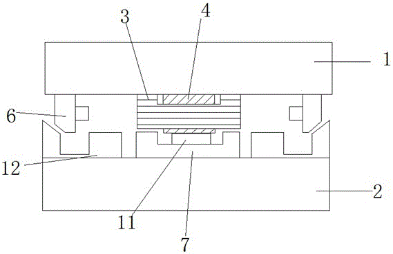
Figure 1 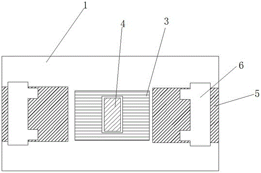
Figure 2 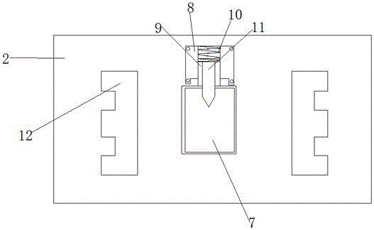
Figure 3
Abstract
Description
technical field
[0001] The invention relates to the technical field of automobile molds, in particular to a mold for side punching, trimming, and turning holes of automobile parts. Background technique
[0002] Under the correct guidance of the national industrial policy, after decades of hard work, the design and manufacturing capabilities of stamping dies in my country have reached a relatively high level, and many modern design and manufacturing technologies, including information engineering and virtual technology, have been applied in many mold companies. Even so, there is still a big gap between my country's stamping die design and manufacturing capabilities, market demand and the international advanced level. These are mainly manifested in high-end cars and large and medium-sized car panel molds and high-precision punching dies. There is a big gap in terms of design, processing technology and capabilities. The car panel mold has the characteristics of difficult desig...
Examples
Embodiment Construction
[0017] The following will clearly and completely describe the technical solutions in the embodiments of the present invention with reference to the accompanying drawings in the embodiments of the present invention. Obviously, the described embodiments are only some, not all, embodiments of the present invention.
[0018] refer to Figure 1-3 , the automobile side punching, trimming and turning over mold, including an upper template 1 and a lower template 2, the upper template 1 is connected with the stamping machine, and the lower template 2 is fixed on the base, the upper template 1 is provided with a binder plate 3, and The binder plate 3 is provided with an opening, and the trimming punch 4 is provided in the opening, and the tops of the binder plate 3 and the trimming punch 4 are fixedly connected with the bottom of the upper template 1, and the trimming punch 4 extends to The outer side of the binder plate 3, and a gap is provided between the trimming punch 4 and the bind...