Clamp device for machining large-sized thin-walled impeller and finish machining method of large-sized thin-walled impeller

The technology of a fixture device and an impeller, which is applied in the direction of clamping device, positioning device, manufacturing tool, etc., can solve the problems of inaccurate positioning, reduced machining accuracy, and reduced machining accuracy, so as to improve the positioning quality, avoid direct damage, The effect of improving surface accuracy

Inactive Publication Date: 2016-10-26
HIMILE MECHANICAL SCI & TECH (SHANDONG) CO LTD
View PDF7 Cites 13 Cited by
  • Summary
  • Abstract
  • Description
  • Claims
  • Application Information

AI Technical Summary

Problems solved by technology

[0003] 1) Since the impeller wall is relatively thin, especially for large thin-walled closed impellers, the thinnest part is less than 1.2mm, direct clamping is easy to cause deformation and rupture, causing damage to the impeller, which will not only further bring troubles for subsequent machining Difficulty, and in most cases, after the impeller is damaged, the impeller will be scrapped, which greatly increases the production cost;
[0004] 2) Due to the complexity of the clamping tool, more surfaces on the impeller have not been machined, which greatly reduces the precision of turning;
[0005] 3) The impeller is directly set on the impeller support base plate, without an effective positioning of the impeller, it is prone to radial deviation, so it is easy to cause cracks on the surface of the impeller due to vibration during the turning process, and at the same time, there are large Potential safety hazards, further reducing processing accuracy;
[0006] 4) Fixtures for processing cannot play a role in fast positioning, so more time is wasted for clamping and alignment
[0008] 6) The impeller is a casting, the overall surface roughness is poor, the positioning is not accurate, the efficiency of fixed alignment is low, the machining accuracy is reduced during turning, and it is easy to deform the workpiece, resulting in low yield

Method used


Image

  • Clamp device for machining large-sized thin-walled impeller and finish machining method of large-sized thin-walled impeller
  • Clamp device for machining large-sized thin-walled impeller and finish machining method of large-sized thin-walled impeller
  • Clamp device for machining large-sized thin-walled impeller and finish machining method of large-sized thin-walled impeller

Examples


Embodiment 1

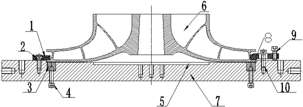
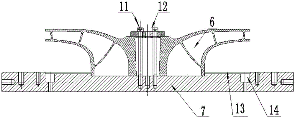
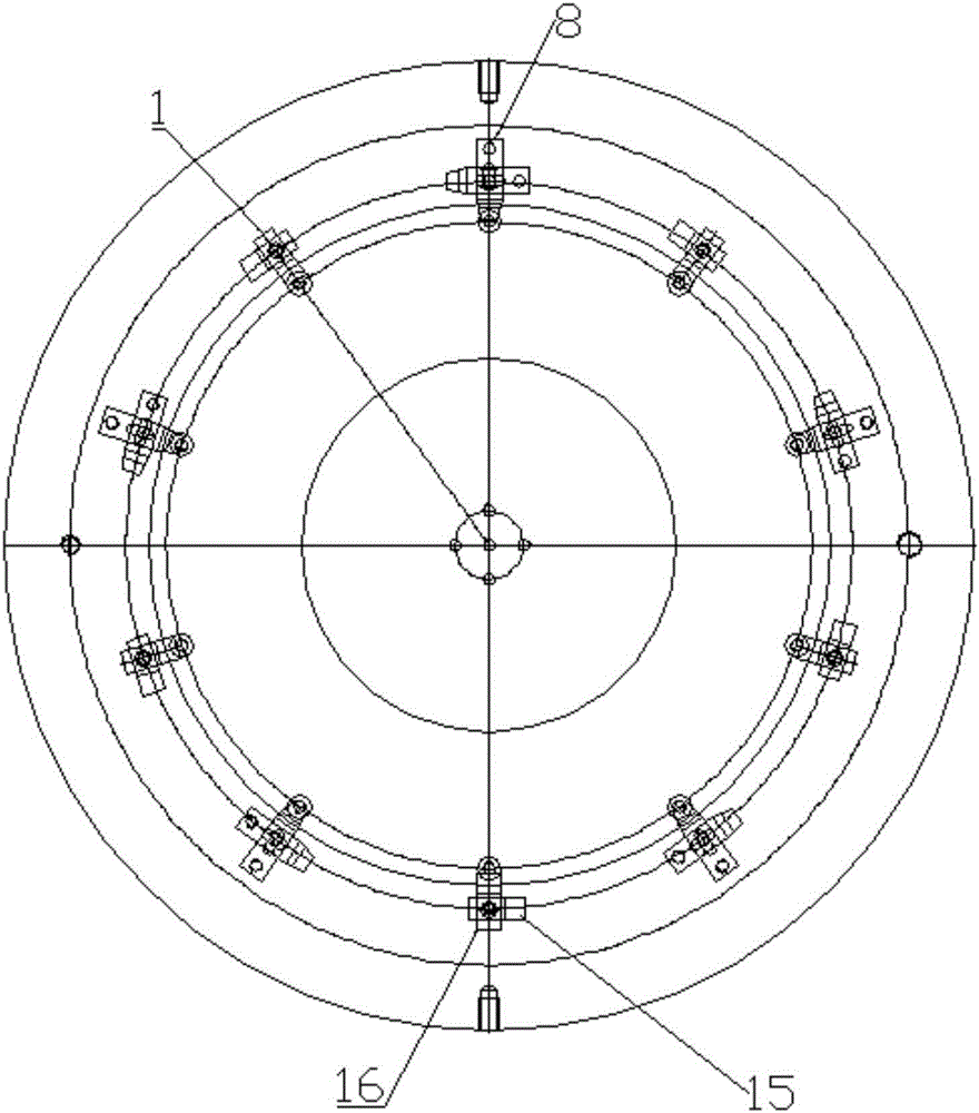
[0054] The fixture device for large-scale thin-walled impeller machining includes a base plate 7, on the upper surface of the base plate 7 there are two first and second recesses for clamping the end face of the impeller, because one end face of the impeller 6 is large and the other is small, Therefore, the first recess and the second recess are figure 1 The large positioning circle 13 and the small positioning circle 5 are movable on the working surface of the bottom plate 7. A plurality of pressing blocks 8 are used as the first pressing parts and a plurality of positioning blocks 1 are used as the positioning parts. The positioning blocks realize the alignment of the impeller. The positioning of the processing reference, the processing reference is the inner surface of the lower blade of the impeller, which can realize rapid positioning, the pressing block 8 can be rotatably fixed on the bottom plate 7, and when the small positioning circle 5 is matched with the second round...

Embodiment 2

[0060] The fixture device for machining large thin-walled impellers includes a bottom plate. The working surface of the bottom plate is provided with a concave part. The concave part is matched with the working surface where the large round surface of the impeller end is located. The edge of the concave part is provided for locking the first round surface of the impeller end to the bottom plate. The first pressing part is detachably provided on the working surface of the bottom plate for locking the second round surface of the impeller end to the bottom plate. The second pressing part is provided with the second pressing part.

[0061] This solution omits the second recess in the first solution, which can also satisfy the rapid positioning of the impeller. At this time, the fastening plate in the second pressing part is preferably fastened by the bolts arranged in a triangle, so as to improve stability sex.

[0062] Other structures in this embodiment are the same as those in ...

Embodiment 3

[0064] A method for finishing a large thin-walled impeller, the specific steps are as follows:

[0065] 1. Fix the bottom plate 7 on the workbench of the machine tool and align it;

[0066] 2. Clean up the adjustment block groove 14, place the adjustment block 3 in the adjustment block groove 14, and adjust the positioning block 1 and the pressing block 8 to the open position 15;

[0067] 3. Clean the burrs on the bottom surface of the impeller 6, and place the large round bottom surface of the impeller 6 after rough turning in the large positioning circle 13;

[0068] 4. Adjust the positioning block 1 to the closed position 16, and then tighten the corresponding adjusting bolt 4 upwards, so that each adjustment block 3 is in contact with the lower blade of the impeller, and the positioning block is in close contact with the reference surface of the impeller;

[0069] 5. Adjust the compression block 8 to the closed position, then tighten the corresponding adjustment bolt 4 up...


PUM


Abstract

The invention discloses a fixture device for machining large-scale thin-walled impellers and a finishing method for large-scale thin-walled impellers. The fixture device includes a bottom plate, and the working surface of the bottom plate is provided with a first recess and a second recess. The circular surface fits, and the second concave part cooperates with the second circular surface of the impeller end. The edge of the first concave part is provided with a first pressing part for pressing the impeller wall, and the center of the second concave part is detachably provided with a The second circular surface is locked to the second pressing part of the bottom plate. In the present invention, the first circular surface at the end of the impeller is positioned by setting the first recess, and the impeller is locked to the bottom plate through the first pressing part without welding. The fixing is convenient and fast. After the first round of machining of the impeller, the second concave part is set to position the second circular surface of the impeller, and the second pressing part is used to fasten the impeller to realize sequential machining of the impeller. Avoid the situation that some surfaces are not processed due to fixtures or other reasons, and improve the surface accuracy of the impeller.

Description

technical field [0001] The invention relates to the field of impeller processing, in particular to a fixture device for machining large-scale thin-walled impellers and a finishing method for large-scale thin-walled impellers. Background technique [0002] Centrifugal compressors or centrifugal pumps are used to provide pressurization for various fluid flows. This type of compressor or centrifugal pump contains an impeller. When the impeller rotates, the fluid enters in the axial direction, and then accelerates into the circumferential and radial directions. The high-velocity fluid enters the diffuser, and the high-pressure fluid is output after the speed is converted. For this type For compressors or centrifugal pumps, the impellers used are generally large thin-walled alloy precision casting impellers. No matter what kind of impeller, after casting or manufacturing, it is necessary to machine the impeller such as turning, heat treatment, and high-speed test before it can b...

Claims


Application Information

Patent Timeline
Patent Type & Authority Applications(China)
IPC IPC(8): B23Q3/12B23B1/00B23B5/00
CPCB23Q3/12B23B1/00B23B5/00B23Q2703/10
Inventor 张伟范纪成韩桂强孙日文
Owner HIMILE MECHANICAL SCI & TECH (SHANDONG) CO LTD
Why Eureka
Try Eureka