Fabricated steel frame and steel plate shear wall structure replaceable after earthquake

A steel plate shear wall and steel frame technology, applied in the direction of walls, building components, building structures, etc., can solve economic losses, cannot meet the rapid repair of lifeline projects, beam end nodes, embedded steel plates and connectors cannot be replaced to reduce economic losses, increase the speed of structural construction, and reduce repair time

Inactive Publication Date: 2016-10-26
BEIJING JIAOTONG UNIV
View PDF5 Cites 14 Cited by
  • Summary
  • Abstract
  • Description
  • Claims
  • Application Information

AI Technical Summary

Problems solved by technology

The traditional wall panel connection form is the welded connection between the wall panel and the fishplate, and the fishplate is welded to the frame beam and frame column. This welding connection means that after a strong earthquake, although the steel column and the main steel beam can still maintain elasticity, However, the damaged beam end joints, embedded steel plates and connectors cannot be replaced, resulting in huge economic losses and unable to meet the urgent need for rapid repair of lifeline projects. Therefore, a steel frame and steel plates that can replace the damaged position after the earthquake are proposed The shear wall structure system is very necessary

Method used


Image

  • Fabricated steel frame and steel plate shear wall structure replaceable after earthquake
  • Fabricated steel frame and steel plate shear wall structure replaceable after earthquake
  • Fabricated steel frame and steel plate shear wall structure replaceable after earthquake

Examples


Embodiment Construction

[0041] In order to illustrate the present invention more clearly, the present invention will be further described below in conjunction with preferred embodiments and accompanying drawings. Similar parts in the figures are denoted by the same reference numerals. Those skilled in the art should understand that the content specifically described below is illustrative rather than restrictive, and should not limit the protection scope of the present invention.

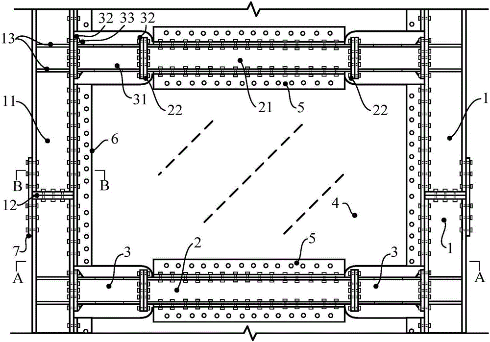
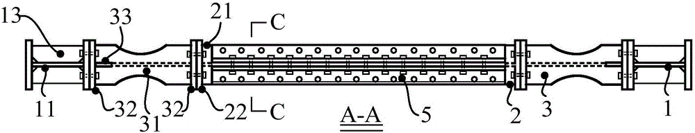
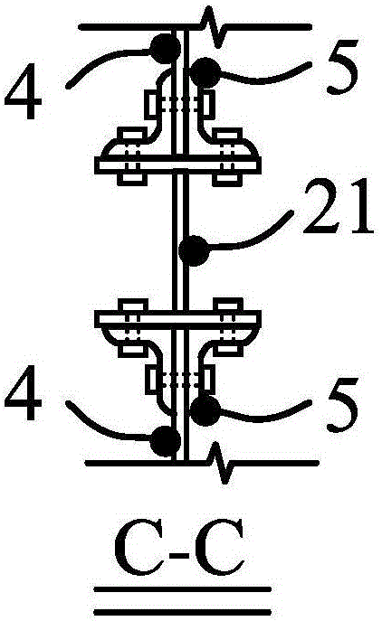
[0042] like Figure 1-Figure 17 As shown, a post-earthquake replaceable assembled steel frame and steel plate shear wall structure includes frame steel columns 1, main steel beams 2, post-earthquake replaceable energy-consuming nodes 3 and post-earthquake replaceable embedded steel plates 4.

[0043]The frame steel column 1 includes a column body 11 , a first end plate 12 , a cover plate 7 and a column angle steel 6 , and the node domain stiffeners 13 are fixed on the column body 11 . The web of the column 11 is connected...


PUM


Abstract

The invention discloses a fabricated steel frame and steel plate shear wall structure replaceable after an earthquake. The fabricated steel frame and steel plate shear wall structure comprises frame steel columns, main steel beams, post-earthquake replaceable energy dissipating joints and post-earthquake replaceable embedded steel plates. Webs of column bodies of the frame steel columns are connected through first end plates. Second end plates of each main steel beam are fixedly arranged at the two ends of a corresponding beam body. Third end plates of each post-earthquake replaceable energy dissipating joint are fixedly arranged at the two ends of a corresponding beam section, and connected with the corresponding second end plate of the corresponding beam body and an inner flange of the corresponding column body through bolts correspondingly. The post-earthquake replaceable embedded steel plates are connected with the inner flanges of the corresponding column bodies and the corresponding beam bodies through bolts, and long grooves are formed in the portions, making contact with the corresponding post-earthquake replaceable energy dissipating joints, of the four corners of each post-earthquake replaceable embedded steel plate. Internal force can be effectively transmitted, and it is guaranteed that the structural integrity and stress performance are given to full play; and structural failure and a failure mechanism are actively controlled, it is guaranteed that a main body structure is kept in an elastic state, plastic energy dissipation and damage occur in designated local positions, post-earthquake replacement and repairing are facilitated, and economic loss is reduced.

Description

technical field [0001] The invention relates to the technical field of lateral force resistant structures, in particular to a replaceable assembled steel frame and steel plate shear wall structure after an earthquake. Background technique [0002] Based on the urgent need for the construction of high-rise and super high-rise buildings and the current situation of frequent strong earthquakes, steel frame and steel plate shear wall structures have developed rapidly in recent years as a structural system with excellent lateral resistance. Compared with the traditional steel frame system, it has larger initial lateral stiffness and higher shear bearing capacity after buckling; compared with the traditional steel frame and concrete shear wall system, its material is consistent, deformation is easy to coordinate, ductility It is easy to match, easy to connect and construct, and it can avoid the rapid decrease of the bearing capacity of the steel frame as the second line of defense...

Claims


Application Information

Patent Timeline
Patent Type & Authority Applications(China)
IPC IPC(8): E04B1/19E04B1/58E04B2/58
CPCE04B1/19E04B1/1903E04B1/58E04B2/58
Inventor 王萌杨维国
Owner BEIJING JIAOTONG UNIV
Why Eureka
Try Eureka