Water treatment system

A water treatment system and water outlet technology, applied in the field of water treatment, can solve the problems that the anaerobic flora and aerobic flora can not be used at the same time, and the A2/O occupies a large area, so as to save the occupied area, The effect of energy saving

Inactive Publication Date: 2016-11-09
上海立泉环境科技有限公司
View PDF10 Cites 2 Cited by
  • Summary
  • Abstract
  • Description
  • Claims
  • Application Information

AI Technical Summary

Problems solved by technology

However, the disadvantage of the SBR method is that on the one hand, it has higher requirements on the control system. On the other hand, since the anaerobic and aerobic reactions are carried out alternately, its essence is to complete the anaerobic reaction and aerobic reaction alternately in the...

Method used


Image

  • Water treatment system
  • Water treatment system
  • Water treatment system

Examples


Embodiment 1

[0089] The wastewater is: wastewater from a printing and dyeing factory in Shaoxing City, Zhejiang Province: the effluent COD is 2800mg / L, and the total nitrogen is 65mg / L.

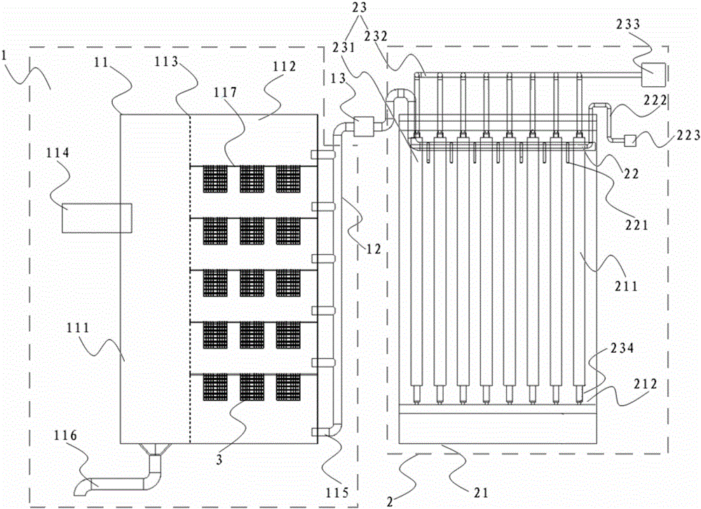
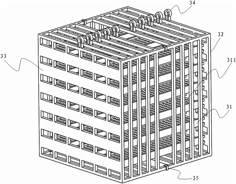
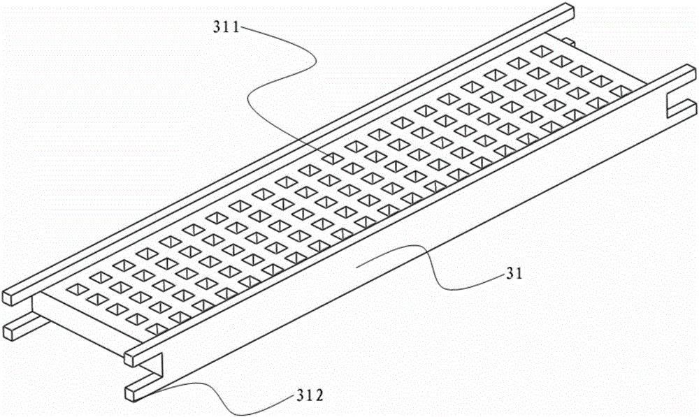
[0090] The structure of the anaerobic reaction device: the length of the anaerobic reaction tank is 7m, the width is 6m, the height is 15m, and the size of the grid gap of the fine grid is 10mm. The number of layers of fixed packing is 5 layers, and each layer of packing is divided into 2 rows, and the number of packing in each row is 3. The fixed packing is a cube with a side length of 1m, and the packing frame is made of polyvinylchloride (polyvinylchloride) after hydrophilic treatment. ), the material of the filler support is alumina, the hole area of ​​the filler hole on the filler support accounts for 20% of the surface area of ​​the filler support, and the microorganisms domesticated on the filler support are Thiobacillus denitrificans, Nitratereducing bacteria, A combination of Desulfotomaculum and...

Embodiment 2

[0095] The wastewater is: wastewater from a paper mill in Shanghai: the effluent COD is 4900mg / L, and the total nitrogen is 45mg / L.

[0096] The structure of the anaerobic reaction device: the length of the anaerobic reaction tank is 12m, the width is 9m, the height is 20m, and the size of the grid gap of the fine grid is 8mm. The number of layers of fixed packing is 6 layers, and each layer of packing is divided into 2 rows, and the number of packing in each row is 5. The fixed packing is a cube with a side length of 1.5m, and the packing frame is polystyrene ( polystyrene), the material of the packing support is metal iron material, the pore area of ​​the packing hole on the packing support accounts for 35% of the surface area of ​​the packing support, and the microorganisms domesticated on the packing support are Thiobacillus denitrificans and Nitratereducing bacteria. bacteria, usually bacteria that can reduce nitrate, belonging to the combination of denitrifying bacteria)...


PUM

PropertyMeasurementUnit
Lengthaaaaaaaaaa
Lengthaaaaaaaaaa
Widthaaaaaaaaaa

Abstract

The invention relates to the field of water treatment, in particular to a water treatment system, which comprises an anaerobic reaction device and an aerobic reaction device, wherein the anaerobic reaction device is in fluid communication with the aerobic reaction device; the anaerobic reaction device comprises an anaerobic reaction tank body and a grid for dividing an internal space of the anaerobic reaction tank body into an isolated area and a filler area which are in fluid communication with each other; a water inlet of the anaerobic reaction device is positioned in the isolated area; a water outlet of the anaerobic reaction device is positioned in the filler area; an anaerobic reaction filler is arranged in the filler area. According to the water treatment system, systems for an A2O water treatment method can be effectively integrated, and in addition, air can float to wash the surface of a filter membrane, so that the effects of greatly reducing the energy consumption and saving an occupied area can be achieved.

Description

technical field [0001] The invention relates to the field of water treatment, in particular to a water treatment system. Background technique [0002] In recent years, with the rapid development of the national economy, the discharge of industrial wastewater has continued to increase, and the difficulty of treatment has continued to increase. Especially in cities with tight land use, the treatment of industrial wastewater has become an urgent problem for enterprises to solve. [0003] As the core link of industrial wastewater treatment, biochemical treatment directly restricts the overall treatment effect of industrial wastewater. The traditional biochemical treatment needs to distribute the pretreated wastewater into the anaerobic pond, aerobic pond, and sedimentation pond, and then meet the discharge requirements after advanced treatment, which is commonly referred to as the A2 / O treatment method. A2 / O can make pollutants complete anaerobic and aerobic biochemical degrad...

Claims


Application Information

Patent Timeline
IPC IPC(8): C02F3/30C02F3/12C02F3/28C02F3/34C02F9/14B01D65/02B01D65/08
CPCB01D65/02B01D65/08C02F1/444C02F3/1268C02F3/1284C02F3/2806C02F3/30C02F3/34C02F9/00C02F2203/006Y02W10/10
Inventor 王鸿洋李恒
Owner 上海立泉环境科技有限公司
Why Eureka
Try Eureka