Axially through H-type finned tube and heat exchange tube bundle thereof

A technology of heat exchange tube bundles and finned tubes, which is applied in the field of H-shaped finned tubes, can solve the problems of not much change in the general structure, reduced heat transfer and anti-fouling performance, and insufficient normal height of the fins. Achieve the effects of eliminating the initial area of ​​ash accumulation, good heat transfer and anti-fouling characteristics, and strong industrial application value

Inactive Publication Date: 2016-11-09
XI AN JIAOTONG UNIV
View PDF11 Cites 15 Cited by
  • Summary
  • Abstract
  • Description
  • Claims
  • Application Information

AI Technical Summary

Problems solved by technology

[0004] Judging from the existing patent situation, the patent 201120443516.5 proposes an elliptical H-shaped finned tube. Compared with the round tube, the elliptical tube does reduce the flow resistance to a certain extent, but because the general structure has not changed much, Without destroying the vortex stagnation zone, the improvement of the dust accumulation is relatively limited
Patents 201420286535.5 and 201420300136.X both provide heat transfer enhancement by adding some kind of longitudinal vortex generator, but compared with this patent, the longitudinal vortex generator disclosed in the above patent has a Insufficient height, when the pitch between fins is large, the heat transfer and anti-fouling performance will be reduced
The three patents disclosed in patents 201410290408.7, 201420343697.8 and 201420343761.2 are all through various deformations on the outer edges of the fins of conventional H-shaped finned tubes to achieve heat transfer on discontinuous surfaces, although this structure can effectively improve the heat transfer rate. The finning ratio of the heat pipe reduces the pitch of the fins, but under the high-speed airflow containing ash, the outer wear of the fins will be more serious, reducing the life of the finned tubes

Method used


Image

  • Axially through H-type finned tube and heat exchange tube bundle thereof
  • Axially through H-type finned tube and heat exchange tube bundle thereof
  • Axially through H-type finned tube and heat exchange tube bundle thereof

Examples


Embodiment 1

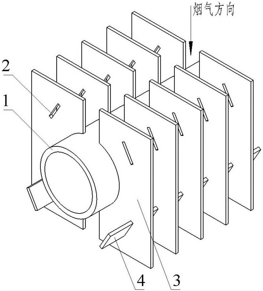
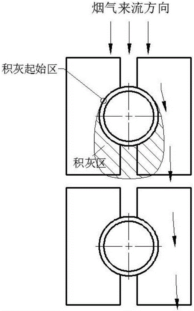
[0036] figure 1 It is a schematic diagram of a conventional H-shaped finned tube with a rectangular deflector in Embodiment 1 of the present invention.

[0037]The structure includes a base tube part, a fin part and a through part, the base tube part includes at least one base tube 1; the fin part is a plurality of parallel fins arranged along the axis of the base tube and connected to the outer wall of the base tube 1 group, wherein the fin group includes two fins 3 symmetrically arranged on both sides of the base tube, the two fins are regularly arranged according to a certain pitch, and the inner side of each fin has a groove matching the outer wall of the base tube; through The part includes a through-slot 2 that is partially processed on the surface of the fin along the flow direction of the flue gas and arranged relative to the base pipe, and a guide vane 4 is provided on the side where the flue gas flows out to pass through all the through-slots 2 on the side where the ...

Embodiment 2

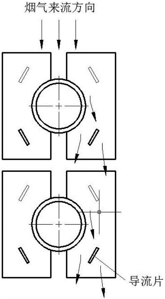
[0042] image 3 It is a schematic diagram of fin structures with different through-slot shapes under the same fin surface shape in Embodiment 2 of the present invention. In this embodiment, the same symbols are assigned to the same structures as in the first embodiment, and the same descriptions are omitted.

[0043] Such as image 3 As shown, in the axially penetrating H-shaped finned tube of the present invention, the through groove 2 is not limited to the rectangular groove in the first embodiment, and the shape of the through groove 2 can also be arc-shaped or circular. For rectangular slots, the rectangular long side of the flue gas flow side is used as the slotting reference direction, and the angle of attack between the slotting direction and the gas flow direction is 10° to 80°; for arc-shaped slots, the flue gas flow side The secant line where the arc of the groove is located is taken as the reference direction of the groove, which is 10°-80° from the gas flow direc...

Embodiment 3

[0045] 4 is a schematic surface view of H-shaped finned tubes with rectangular deflectors under different fin surface shapes in Embodiment 3 of the present invention. In this embodiment, the same symbols are assigned to the same structures as in the first embodiment, and the same descriptions are omitted.

[0046] As in Figure 4 Figure 4a and Figure 4b As shown, the surface shape of the fin 3 is not limited to the rectangle in the first embodiment, and may also be a parallelogram, trapezoid or other irregular quadrilateral.


PUM


Abstract

The invention relates to an axially through H-type finned tube and a heat exchange tube bundle thereof. The H-type finned tube comprises a base tube part, a fin part and a through part, wherein the base tube part comprises at least one base tube; the fin part comprises a plurality of parallel fin groups which are arranged in the axial direction of the base tube and connected with the outer wall of the base tube; each fin group comprises two fins which are symmetrically arranged on two sides of the base tube and regularly arranged according to a certain pitch; a groove matched with the outer wall of the base tube is formed in the inner side of each fin; the through part comprises through grooves that are processed in parts of the surfaces of the fines in a smoke flowing direction and arranged relative to the base tube; and flow deflectors passing through the corresponding through grooves are arranged on a smoke outlet side and connect the fin groups in series in the axial direction of the base tube to change the axial cross section of the H-type finned tube from a plane into a three-dimensional structure. According to the axially through H-type finned tube and the heat exchange tube bundle thereof, an initial region of ash deposition can be effectively eliminated, a flow stagnation region on the leeward side of the finned tube is obviously reduced, and ash deposited on the side surfaces of the fins and the base tube in the flow stagnation region is greatly reduced; meanwhile, the heat transfer effect of the H-type finned tube is effectively enhanced; and the through grooves can be formed by punching, so that automatic production can be realized easily.

Description

technical field [0001] The invention relates to an H-shaped finned tube, in particular to an axially penetrating H-shaped finned tube and its heat exchange tube bundle, which is suitable for various types of heat exchangers in industries such as power, petroleum, chemical industry, refrigeration, and metallurgy. Heat and heating equipment. Background technique [0002] With the sustained and rapid development of my country's economy, the problem of energy supply shortage has become increasingly prominent, and energy conservation, emission reduction and consumption reduction have become the inevitable requirements of my country's economic and social development. As an important part of industrial processes such as power, petroleum, chemical industry, refrigeration, metallurgy and even aviation / rocket, heat exchangers are of great significance for their safe and efficient operation. In various heat exchange equipment, increasing the heat exchange area through fins is a common...

Claims


Application Information

Patent Timeline
Patent Type & Authority Applications(China)
IPC IPC(8): F28F1/30F28D1/04
CPCF28D1/04F28F1/30
Inventor 赵钦新焦健王云刚梁志远
Owner XI AN JIAOTONG UNIV
Why Eureka
Try Eureka