Building method of carbon fiber composite material cutting model

A technology for composite materials and establishment methods, which is applied in the research field of cutting and processing of carbon fiber composite materials, and can solve problems such as establishment methods that do not consider interface cracking

Active Publication Date: 2016-11-09
DALIAN UNIV OF TECH
View PDF3 Cites 15 Cited by
  • Summary
  • Abstract
  • Description
  • Claims
  • Application Information

AI Technical Summary

Problems solved by technology

There is no carbon fiber composite material cutting model and its establishment method that can characterize fiber fracture, resin, interface cracking, and flank surface fiber extrusion

Method used


Image

  • Building method of carbon fiber composite material cutting model
  • Building method of carbon fiber composite material cutting model
  • Building method of carbon fiber composite material cutting model

Examples


Embodiment 1

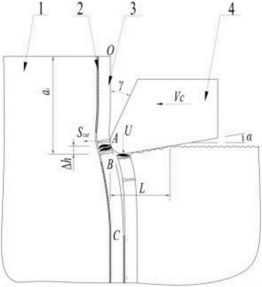
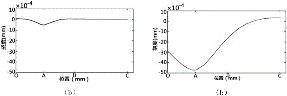
[0099] Calculate the depth of cut a from the conclusion of the first step c 20μm and 50μm fiber deformation and interface cracking respectively. The material parameters of the carbon fiber composite material 1 used and the matrix 2 and fiber 3 are shown in Table 1. The cutting speed is V c =500mm / min, cutting angle θ=90°. The result is as figure 2 shown. When the minimum depth of cut is 20 μm, the fiber 3 only undergoes small local deformation under the action of the cutting force, and the fiber 3 shears and breaks, but the interface does not crack, as shown in figure 2 As shown in (a), when the maximum depth of cut is 50 μm, the fiber 3 bends and deforms greatly under the action of cutting force, the interface cracks first and then the fiber 3 bends and breaks, as shown in Fig. figure 2 (b) shown. Through comparison, it is found that when the arc radius of the blade is much smaller than the fiber radius, the local contact stress is greater than the bending stress, an...


PUM


Abstract

The invention belongs to the field of carbon fiber composite material cutting and processing researching, and relates to a building method of a carbon fiber composite material cutting model. The building method comprises the steps that firstly, a bidirectionally matrix-constrained single-fiber cut-off model is built, wherein the fiber deformation characteristics are described in three segments through the boundary condition difference in the fiber length direction according to the differences of the fiber stress and the borne matrix constraining action of the model in the fiber direction, the first segment starts from the top end to a cutting edge contact point, the second segment starts from the cutting edge contact point to a cutting plane, and the third segment starts from the cutting plane to a certain point far away from a processing surface; secondly, a contact model and a single-fiber compression-shearing model for a cutting edge and fibers are built; lastly, a composite material cutting force model is built. According to the method, fiber breakage, resin interface crack and the extruding action of a rear cutter surface on the fibers can be represented, a quantitative relation between the cutting force and processing parameters in composite material cutting and processing can be obtained, and an experimental basis is provided for actual cutter design and technological parameter establishment.

Description

technical field [0001] The invention belongs to the research field of cutting processing of carbon fiber composite materials, and relates to a method for establishing a cutting model of carbon fiber composite materials. Background technique [0002] Carbon fiber composite materials have high specific strength, high specific stiffness, and can be designed and manufactured in an integrated manner with material structure and performance. It has become the preferred material for significantly improving the performance and reliability of aerospace equipment. The integrally manufactured composite parts are large in size and complex in structure, and a large number of edge contours, functional windows and connection holes still need to be cut and processed to achieve assembly. [0003] Carbon fiber composite material is a material composed of discretely distributed carbon fibers bonded together through a matrix. The matrix is ​​wrapped around the carbon fibers, that is, it is in a ...

Claims


Application Information

Patent Timeline
Patent Type & Authority Applications(China)
IPC IPC(8): G06F17/50
CPCG06F30/17G06F30/20G06F2119/18
Inventor 贾振元宿友亮毕广健牛斌王福吉
Owner DALIAN UNIV OF TECH
Why Eureka
Try Eureka