Automatic control type circulating water tank for simulating instantaneous dam break

A technology of circulating water tank and circulating water pump, which is applied in the direction of educational appliances, teaching models, instruments, etc., can solve the problems of affecting the flow state, time-consuming, and difficult to accurately control the opening speed of the gate, so as to achieve high accuracy and improve experimental efficiency. Effect

Active Publication Date: 2016-11-09
ZHEJIANG UNIV
View PDF6 Cites 16 Cited by
  • Summary
  • Abstract
  • Description
  • Claims
  • Application Information

AI Technical Summary

Problems solved by technology

However, there are many defects in the existing dam break tanks: (1) After the gate is opened, the liquid fills the entire tank. Before starting the next set of experiments, it is necessary to manually move the downstream liquid back to the upstream after the gate is closed. If it is a dry bed experiment, manual work is required It is time-consuming and labor-intensive to wipe the downstream water tank clean with a rag; (2) Due to the uncertainty of the peak value collected by the existing pressure sensor and the repeatability of the experiment, the general dam break experiment needs to be repeated hund

Method used


Image

  • Automatic control type circulating water tank for simulating instantaneous dam break
  • Automatic control type circulating water tank for simulating instantaneous dam break
  • Automatic control type circulating water tank for simulating instantaneous dam break

Examples


Embodiment Construction

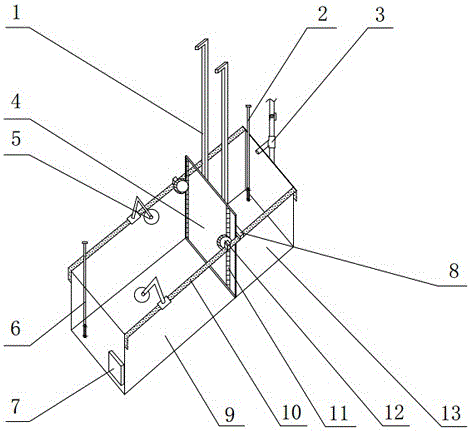
[0029] The specific implementation manners of the present invention will be described in further detail below in conjunction with the accompanying drawings.

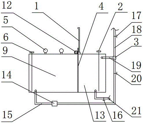
[0030] Such as figure 1 As shown, the present invention includes a water tank, a gate, a water level control system and a gate lifting control system, wherein the water tank is divided into two parts by the gate door plate 4, which are respectively a water tank 13 upstream of the gate and a water tank 9 downstream of the gate, and the upper edge of the water tank in the length direction of the water tank is fixed. A pair of guide rails 10 along the upper edge of the water tank are provided. Such as figure 2As shown, the water level control system of the present invention includes a water injection pipe 18, a water inlet pipe 19, a water guide pipe 15 and an industrial control computer 7 connected by a three-way pipe fitting 3, wherein the water injection pipe 18 is provided with a first electromagnetic valve 17, and th...


PUM


Abstract

The invention belongs to the field of hydraulic experimental model facilities and particularly relates to an automatic control type circulating water tank for simulating the instantaneous dam break. The circulating water tank comprises a water tank, a gate, a water level control system and a gate lifting control system. The water level control system comprises a water injection pipe, a water inlet pipe and a water guide pipe which are connected through a three-way pipe fitting, wherein the water guide pipe is connected with a circulating water pump. The water level control system further comprises a gate upstream water level gauge and a gate downstream water level gauge, wherein the gate upstream water level gauge and the gate downstream water level gauge are respectively arranged in a gate upstream water tank and a gate downstream water tank. The gate lifting control system comprises a vertical rack arranged on the front surface of a gate door plank and matched with the driving gear of a motor, and a lifting guide rail fixedly erected on the water tank along a guide rail. During the lifting process of the gate door plank, a pair of vertical guide bars on the back surface of the gate door plank are always fittingly kept in the vertical guide grooves of the lifting guide rail. An automatic air drying device is arranged in the gate downstream water tank, so that the conduction of dry bed experiments is facilitated. The circulating water tank is stable, automatic and efficient.

Description

technical field [0001] The invention belongs to hydraulic experiment model facilities, in particular to an automatic control circulating water tank for simulating instantaneous dam breaks. Background technique [0002] The method of obtaining instantaneous dam-breaking water by opening the gate instantly in a rectangular tank has been used in various fluid-solid coupling experiments, and the interaction between the instantaneous dam-breaking water and its downstream structures is often used to simulate tsunami landing, Natural phenomena such as waves on deck. In addition, the experimental research data of the movement of dam-break water in the dry bed and the lower surface of the wet bed are often used to test the accuracy of various fluid-solid coupling numerical models. The earliest research on dam-break water body can be traced back to 1892, when Ritter published an article discussing the free surface problem of rectangular dam-break water body moving on dry bed. In 195...

Claims


Application Information

Patent Timeline
IPC IPC(8): G09B25/02
CPCG09B25/025
Inventor 赵西增程都陈勇林伟栋张大可胡子俊
Owner ZHEJIANG UNIV
Why Eureka
Try Eureka