
LLC resonant converter with boosted voltage gain

A technology of resonant converter and boosting voltage, applied in the field of power electronic converters, can solve the problems of low converter efficiency, boosted voltage gain, low dead time voltage gain, etc. The effect of voltage gain

Inactive Publication Date: 2016-11-09
SHAANXI UNIV OF SCI & TECH
View PDF1 Cites 13 Cited by
  • Summary
  • Abstract
  • Description
  • Claims
  • Application Information

AI Technical Summary

Problems solved by technology

[0005] The purpose of the present invention is to solve the problem of low voltage gain and low converter efficiency in the stagnation time of the two-stage converter, and proposes an LLC resonant converter with increased voltage gain

Method used


Image

  • LLC resonant converter with boosted voltage gain
  • LLC resonant converter with boosted voltage gain
  • LLC resonant converter with boosted voltage gain

Examples


Embodiment Construction

[0024] The present invention is described in further detail below in conjunction with accompanying drawing:

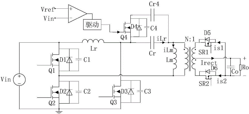
[0025] Such as figure 1 As shown, the present invention includes a DC power supply V in , inverter circuit, resonant circuit, increasing voltage gain network, output rectification filter circuit. The DC power supply is connected with the inverter circuit, the inverter circuit is connected with a resonant circuit in parallel, the resonant circuit is connected with the primary winding of the transformer in series, the resonant circuit is connected with a boosting voltage gain network, and the secondary winding of the transformer is connected with the output rectifying and filtering circuit.

[0026] The half-bridge inverter circuit includes a first switch MOS transistor Q l , the second switch MOS tube Q 2 , the first body diode D l , the second body diode D 2 , the first parasitic capacitance C l and a second parasitic capacitance C 2 . The resonant circuit cons...


PUM


Abstract

The invention discloses an LLC resonant converter with the boosted voltage gain, and the resonant converter comprises a DC power supply (Vin), an inversion circuit, a resonance circuit, a boosted voltage gain network, a transformer, and an output rectification filter circuit. The DC power supply is connected with the inversion circuit, and the inversion circuit is connected with the resonance circuit in a parallel manner. The resonance circuit is in series connection with a primary winding of the transformer, and is connected with the boosted voltage gain network. The secondary winding of the transformer is connected with the output rectification filter circuit. The LLC resonant converter can maintain a higher voltage gain in a dead state (alternating current failure), and is enabled to have higher efficiency at a lower switching frequency. The LLC resonant converter is simple in topological structure, is narrow in frequency change range, is high in efficiency, and is suitable for application occasions where there are two-stage converters and the input voltage is wide in range.

Description

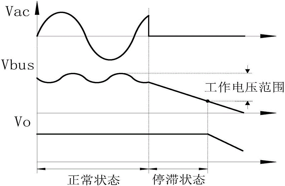
【Technical field】 [0001] The invention belongs to the technical field of power electronic converters, and in particular relates to an LLC resonant converter with increased voltage gain. 【Background technique】 [0002] At present, two-stage ac / dc converters with power factor correction stages are widely used in many industrial occasions. The PFC stage can obtain a higher power factor and provide input voltage for the DC / DC converter of the subsequent stage; A DC / DC converter is used to regulate a stable output voltage. LLC resonant converters are widely used in two-stage structures due to their ability to work in zero-voltage and zero-current switching states, high efficiency, high power density, and transformer-less DC bias current. [0003] An important feature of the two-stage converter is that when the AC power is cut off, the output voltage can be maintained for a period of time, which is called dead time. In order to meet this dead time converter has a higher voltage ...

Claims


Application Information

Patent Timeline
IPC IPC(8): H02M3/335
CPCH02M3/33523H02M3/33576Y02B70/10Y02P80/10
Inventor 史永胜李利李娜王雪丽宁青菊
Owner SHAANXI UNIV OF SCI & TECH
Learn More