Tower tube drying device and drying method for tower tube surface coating
A drying device and drying cylinder technology are applied in chemical instruments and methods, devices for coating liquid on surfaces, coatings, etc., which can solve the problems of high construction cost and long paint construction period, and achieve convenient operation and structure. Simple, low-cost effects
- Summary
- Abstract
- Description
- Claims
- Application Information
AI Technical Summary
Problems solved by technology
Method used
Image
Examples
Embodiment 1
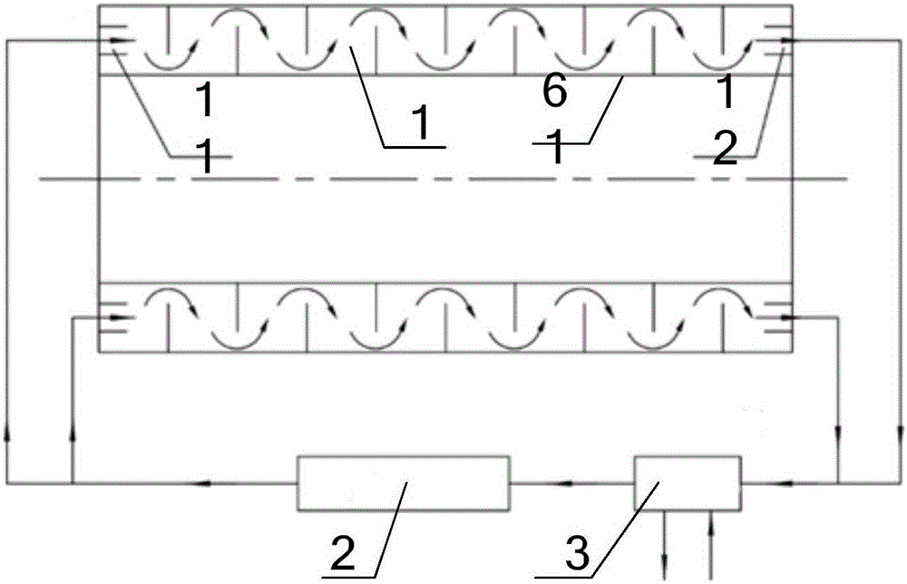
[0035] like figure 1 As shown, the first embodiment provides a tower drying device, which includes a drying channel assembly and a gas heating device 2, the drying channel assembly is used to cooperate with the tower 6 to form a drying gas channel 1, and the gas heating device 2 The gas outlet of the drying gas channel 1 is connected to the gas inlet of the drying gas channel 1, wherein at least a part of the side wall of the drying gas channel 1 is formed by the cylinder wall 61 sprayed with a coating in the tower tube 6. It can be seen that the tower drying device delivers gas to the drying gas passage 1 through the gas heating device 2, since at least a part of the side wall of the drying gas passage 1 is formed by the cylinder wall 61 sprayed with a coating in the tower 6, Therefore, the gas in the drying gas channel 1 can perform heat exchange with the cylinder wall 61 , so that the drying effect can be performed quickly. The tower tube drying device has simple structure...
Embodiment 2
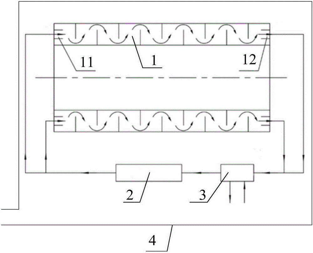
[0045] like figure 2 As shown, the tower drying device provided in the second embodiment is further modified on the basis of the first embodiment. Of course, the second embodiment includes the technical content disclosed in the first embodiment, and the same technical content as the first embodiment will not be repeated. The differences between the second embodiment and the first embodiment will be described below.
[0046] The second tower drying device of the present embodiment also includes an accommodation mechanism, which is provided with an accommodation space for accommodating the gas heating device 2, the gas purification device 3 and the tower tube 6, and the accommodation mechanism is at a position away from the gas outlet of the gas heating device 2 An air inlet is provided. The accommodating mechanism can be a built drying workshop 4, or a large box or shell, which is not limited here.
[0047] Preferably, in order to further reduce the environmental pollution c...
Embodiment 3
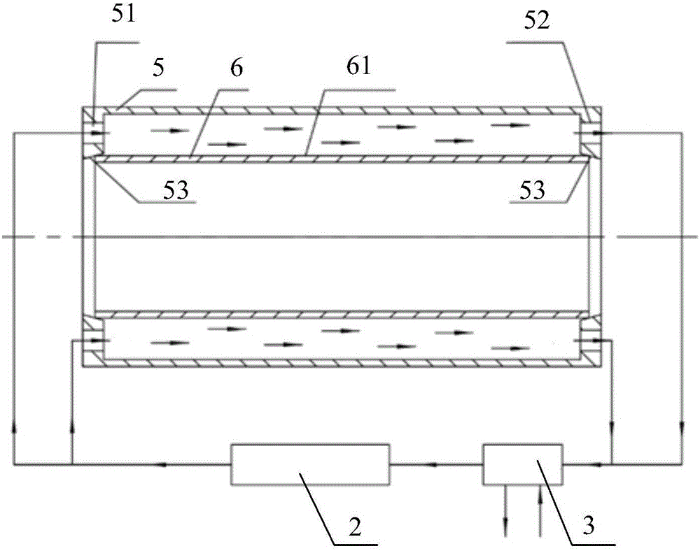
[0050] like Figure 3-4 As shown, the tower drying device provided in the third embodiment is modified on the basis of the first embodiment, and the same technical content as the first embodiment will not be repeated here. The third embodiment and the first embodiment are described below the difference.
[0051] The drying channel assembly includes a drying cylinder 5, an air inlet pipe and an air return pipe. The drying cylinder 5 is used to be sleeved on the outside of the cylinder wall 61 to form a drying space between the drying cylinder 5 and the cylinder wall 61. The air inlet pipe , the drying space, and the air return pipe are sequentially connected to form a drying gas channel 1 . In this way, a part of the drying gas channel 1 is composed of a drying space formed between the drying cylinder 5 and the cylinder wall 61 , that is, the drying space outside the cylinder wall 61 constitutes a heat exchange area. This form of tower drying device can also quickly play a dr...
PUM
 Abstract
Description
Claims
Application Information
 - R&D
- Intellectual Property
- Life Sciences
- Materials
- Tech Scout
- Unparalleled Data Quality
- Higher Quality Content
- 60% Fewer Hallucinations
Browse by: Latest US Patents, China's latest patents, Technical Efficacy Thesaurus, Application Domain, Technology Topic, Popular Technical Reports.
© 2025 PatSnap. All rights reserved.Legal|Privacy policy|Modern Slavery Act Transparency Statement|Sitemap|About US| Contact US: help@patsnap.com


