Slagging device and slagging method for ferromolybdenum smelting furnace

A smelting furnace and ferromolybdenum technology, which is applied in the field of ferromolybdenum smelting metal, can solve the problems of high skill requirements for blocking slag discharge openings, easy operator injury, and high labor intensity of workers, so as to eliminate the bonding phenomenon and avoid The effect of escaping ferromolybdenum slag and reducing the difficulty of cleaning

Active Publication Date: 2017-09-12
JINDUICHENG MOLYBDENUM CO LTD
View PDF7 Cites 0 Cited by
  • Summary
  • Abstract
  • Description
  • Claims
  • Application Information

AI Technical Summary

Problems solved by technology

[0005] The applicant has found that the structure of the traditional slagging outlet 10 and the slagging chute 3 has the following defects through many times of practice and use: 1. Manual operation of slagging and cleaning of the slagging outlet 10 is very easy to cause operator injury, and there is a safety risk ; Two, adopt refractory mud plug 8 to block the slag outlet 10, in the drying process, refractory mud plug 8 can shrink and gap occurs between the slag outlet 10, if the refractory mud plug 8 is blocked deeply, it will not be temporarily There is a problem, but if the refractory mud plug 8 is shallowly blocked, the dried refractory mud plug 8 will be washed out by the melt, and there is a risk that the melt will be ejected from the slag outlet 10
Therefore, the skill requirement for blocking the slag outlet 10 is very high, and the potential safety hazard is also very large; three, adopt the slag outlet 10 of refractory mud plug 8 blockage, if the drying is not thorough, the high temperature will make the refractory mud plug 8 Burst, there is a risk of melt being ejected from the slag outlet; 4. Every time a furnace is smelted, a refractory plug 8 must be used to block the slag outlet in advance. The refractory bricks 3-2 at the plug 8 and the slag discharge chute 3 are in direct contact with the high-temperature melt, and the sticky slag on the surface is frequently cleaned manually, and the labor intensity of the workers is high

Method used


Image

  • Slagging device and slagging method for ferromolybdenum smelting furnace
  • Slagging device and slagging method for ferromolybdenum smelting furnace
  • Slagging device and slagging method for ferromolybdenum smelting furnace

Examples


Embodiment Construction

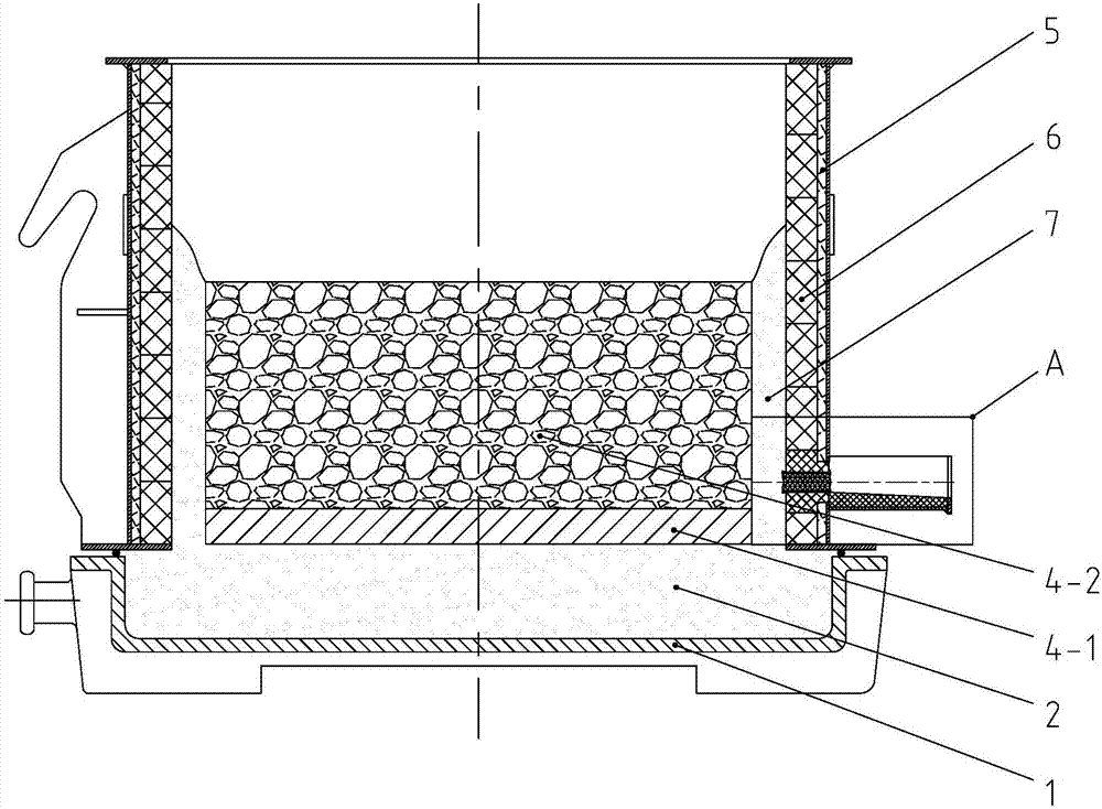
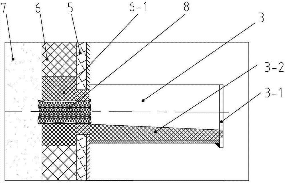
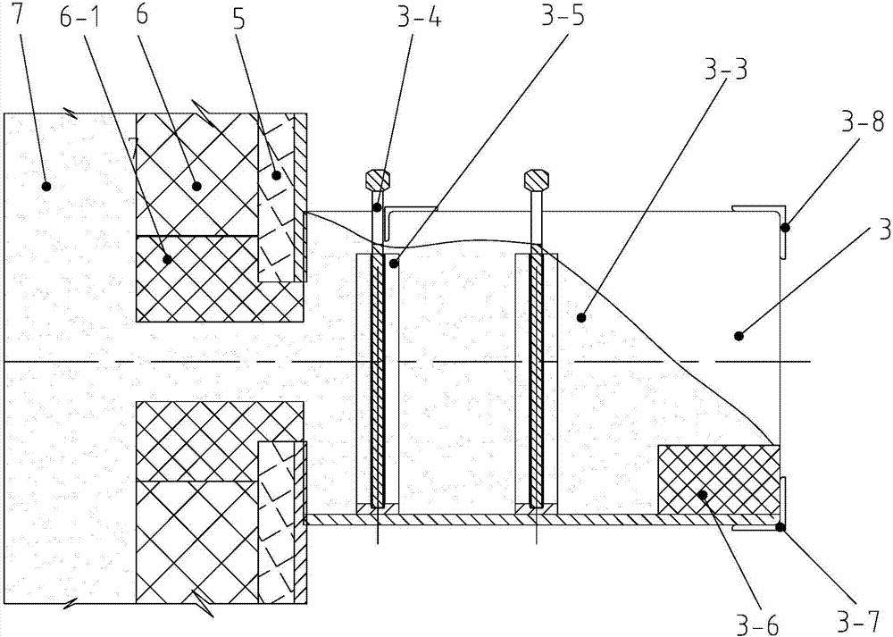
[0038] Such as image 3 , Figure 4 and Figure 5 A kind of slagging device of ferromolybdenum smelting furnace shown, comprises the slag outlet 10 that is opened on the lower side wall of ferromolybdenum smelting furnace, and described slag outlet 10 is connected with slag discharge chute 3, and described slag discharge chute 3 tops The lower part of the opening is closed, and the slag discharge chute 3 is provided with a flashboard 3-4 for dividing it into multiple sections. Quartz sand 3-3 is all filled in the mouth 10 and the slag discharge chute 3 bottoms.

[0039]The present invention fills the slag discharge port 10 and the lower part of the slag discharge chute 3 with quartz sand 3-3, fully utilizes the good temperature resistance, fluidity and low heat conduction of the quartz sand 3-3, and can realize the tight sealing of the slag discharge port 10 Plugging and timely filling of pores can ensure that the slag outlet 10 is reliably blocked. By movably inserting th...


PUM


Abstract

The invention discloses a deslagging device of a ferromolybdenum smelting furnace. The device comprises a slag tap formed in the side wall of the lower portion of the ferromolybdenum smelting furnace, the slag tap is communicated with a deslagging chute, the lower portion of an opening in the upper portion of the deslagging chute is closed, inserting plates used for separating the deslagging chute into a plurality of sections are arranged in the deslagging chute and are movably inserted in the deslagging chute, and the slag tap and the lower portion of the deslagging chute are both filled with silica sand. The invention further discloses a deslagging method using the deslagging device. Through the structural improvement, the silica sand is adopted to serve as a blockage and obstruction material, an effective isolation layer can be formed, heat energy losses are reduced, the burning damage of a high-temperature melt to the deslagging chute is prevented, safety in the smelting process and the deslagging process is ensured, consumption of fireproof materials of the traditional technology is fully reduced, the deslagging operation is quite convenient, the labor intensity is low, and the device is simple, easy to implement, safe and reliable.

Description

technical field [0001] The invention belongs to the field of ferromolybdenum smelting metals, and in particular relates to a slagging device and a slagging method for a ferromolybdenum smelting furnace. Background technique [0002] The structure of the existing ferromolybdenum smelting furnace is as follows figure 1 As shown, it mainly includes a furnace base 1 and a smelting furnace tube 5. The furnace base 1 is cylindrical and its lower end is closed. A cushion layer 2 made of sand is arranged inside the furnace base 1, and the smelting furnace tube 5 is vertically arranged on the cushion layer 2. Above, the inner wall of the smelting furnace barrel 5 is provided with a refractory layer 6 made of refractory bricks, and the smelting furnace barrel 5 is filled with ferromolybdenum ore placed on the cushion layer 2, and the ferromolybdenum ore will be converted into Ferro-molybdenum ingot 4-1 and ferro-molybdenum slag 4-2, ferro-molybdenum ingot 4-1 and ferro-molybdenum sla...

Claims


Application Information

Patent Timeline
Patent Type & Authority Patents(China)
IPC IPC(8): C22C33/04F27D3/15
CPCC22C33/04F27D3/1545F27M2003/13
Inventor 周小宏符新科赵军乌红绪
Owner JINDUICHENG MOLYBDENUM CO LTD
Why Eureka
Try Eureka