Ship elevator safety mechanism and mounting method thereof

A technology of safety mechanism and installation method, applied in the direction of vertical lifting of ship machinery, ship lifting device, building, etc., can solve problems such as catastrophic accidents, and achieve the effect of avoiding catastrophic accidents

Active Publication Date: 2016-11-16
CHINA THREE GORGES CORPORATION +1
View PDF5 Cites 5 Cited by
  • Summary
  • Abstract
  • Description
  • Claims
  • Application Information

AI Technical Summary

Problems solved by technology

However, when the ship lift's full balance system is compromised, it can lead to catastrophic accidents

Method used


Image

  • Ship elevator safety mechanism and mounting method thereof
  • Ship elevator safety mechanism and mounting method thereof
  • Ship elevator safety mechanism and mounting method thereof

Examples


Embodiment 1

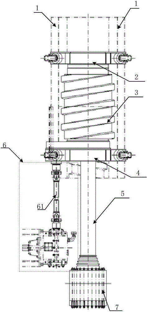
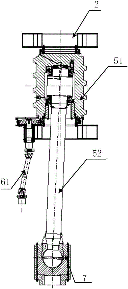
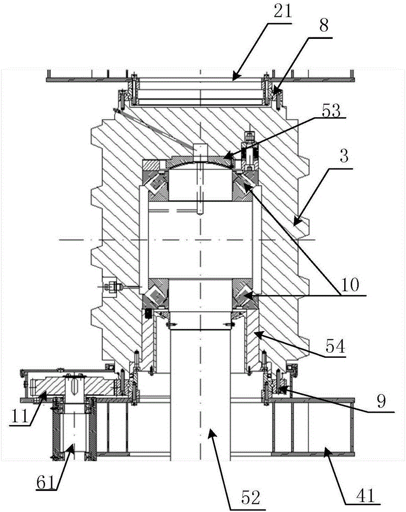
[0035] figure 1 It is a schematic diagram of the structural principle of the safety mechanism of the ship lift provided by Embodiment 1 of the present invention. Such as Figure 1 to Figure 3 As shown, the safety mechanism includes an upper guide frame assembly 2 , a lower guide frame assembly 4 , a safety screw 3 , a support rod assembly 5 and a transmission assembly 6 . The safety screw 3 is vertically arranged in the nut column 1, and the surface of the safety screw 3 is provided with an Archimedes helix, and the equivalent friction angle of the helical surface satisfies the self-locking condition. Keep a certain gap between them, the safety screw 3 is connected with the output shaft end of the reducer of the driving mechanism through the transmission assembly 6, the pitch of the safety screw 3 is an integer multiple of the pitch circle circumference of the pinion of the driving mechanism, through the transmission assembly 6 with an appropriate The transmission ratio guar...

Embodiment 2

[0044] Embodiment 2 is the installation method of the safety mechanism of the ship lift in Embodiment 1, specifically, including the following steps:

[0045] (1) Connect the screw installation machine with the lower ball hinge through the transition flange and bolts, and use the locking sleeve to connect the lower ball hinge with the screw roller of the installation machine, so that the clamping plate of the locking sleeve is closely attached to the flat side of the support rod, Used to transmit torque (according to calculations, the maximum torque that the clamp can provide is much greater than the torque required for screw rotation).

[0046] (2) Adjust the distance D=n*P+2*P between the tread surface of the roller of the spiral drum and the thread of the safety screw by rotating the safety screw, where n is an integer and P is the pitch.

[0047] (3) Install an expansion ring between the support rod and the inner hole at the lower end of the safety screw, and tighten the e...


PUM


Abstract

The invention relates to the technical field of hydropower station navigation structure construction and provides a ship elevator safety mechanism and a mounting method thereof. The safety mechanism comprises an upper guide frame assembly, a lower guide frame assembly, a safety threaded rod, a supporting rod assembly and a transmission assembly. An upper guide frame is arranged at the upper end of the safety threaded rod. A lower guide frame is arranged at the lower end of the safety threaded rod. The supporting rod assembly comprises a supporting rod, a thrust bearing, a pressure-bearing block and a pressure-bearing ring. A spherical hinge is arranged at the lower end of the supporting rod. The transmission assembly comprises a speed reducer, a steering bevel gear case, a clutch, a first gear, a transmission shaft and a universal coupler. The clutch is arranged between the speed reducer and the steering bevel gear case. According to the technical scheme provided by the invention, the safety mechanism is arranged on a ship elevator, and disastrous accidents can be avoided when a full-balance system of the ship elevator is damaged; and meanwhile, when the ship elevator is mounted or maintained, a ship reception chamber can be locked through the safety mechanism.

Description

technical field [0001] The invention belongs to the technical field of construction of navigable structures of hydropower stations, and in particular relates to a safety mechanism of a ship lift and an installation method thereof. Background technique [0002] Ship lift, also known as "ship lift", is a navigable structure that uses mechanical devices to lift ships to overcome the concentrated water level drop on the channel. The ship lift is generally composed of a ship-bearing box, a supporting and guiding structure, a driving device, an emergency device, and a counterweight system. [0003] At present, the counterweight system of large-scale fully balanced vertical ship lifts in the prior art is generally composed of balance reorganization, balance pulley block, wire rope assembly, guide device and other equipment. In the heavy well, the total weight is equal to the total weight of the ship bearing compartment, ship compartment equipment and water body in the compartment....

Claims


Application Information

Patent Timeline
IPC IPC(8): E02C5/00
CPCE02C5/00
Inventor 秦武金海军吴小云刘培军田清伟陈涛
Owner CHINA THREE GORGES CORPORATION
Why Eureka
Try Eureka