Low-specific-speed impeller structure and machining method thereof

A low specific speed, impeller technology, applied in the ultra-low specific speed impeller structure and its processing field, can solve the problem of difficult to ensure the dimensional accuracy and surface finish of the flow channel, the inability to accurately control the height of the welded impeller, and the inability to ensure the realization of the hydraulic performance of the impeller. and other problems, to achieve the effect of reducing the risk of pump accidents, easy to ensure dimensional accuracy, and low molding difficulty

Active Publication Date: 2016-11-16
重庆水泵厂有限责任公司
View PDF6 Cites 7 Cited by
  • Summary
  • Abstract
  • Description
  • Claims
  • Application Information

AI Technical Summary

Problems solved by technology

[0002] With the improvement of energy saving, environmental protection and safety requirements, more and more centrifugal pumps with low specific speed are used, and when the specific speed of the impeller is lower than 35, such as figure 1 For the impeller shown, when the ratio of D2 (impeller outer diameter) to b2 (flow channel outlet width) is greater than 30, the current casting technology of this type of closed impeller is difficult to ensure the dimensional accuracy and surface finish of the flow channel, and the scrap rate is very high. High (generally only about 20% qualified rate), even unable to cast, which limits the further development of ultra-low specific speed centrifugal pumps
[0003] Currently, such impellers are manufactured, see figure 1 Generally, the front cover is processed separately, the blades of the impeller are cast (or processed) together with the rear cover and the hub, and then the front cover and the rear cover are welded to form an integral impeller. This method of forming the impeller, the front There is a weld between the cover plate and the blade, and the weld seam is extremely small, and their bonding strength is low; especially when the diameter of the impeller is large (that is, the value of D2 / b2 is greater than 30), the middle part of the blade and the front cover plate It cannot be welded at all. At this time, the strength of the overall impeller is lower, and the weld seam height of the welded impeller cannot be precisely controlled, which cannot meet the requirements of the hydraulic design size, and cannot guarantee the realization of the hydraulic performance of the impeller; moreover, there is a gap between the blade and the front cover. Great influence on impeller hydraulic performance
At the same time, the welding technology of welding impellers for special materials (duplex steel, non-ferrous metals, etc.) cannot be solved, and the corrosion of the impeller in the heat-affected zone of welding is greatly reduced, which cannot guarantee the long-term use of the impeller, which brings hidden dangers to the safe operation of the equipment.

Method used


Image

  • Low-specific-speed impeller structure and machining method thereof
  • Low-specific-speed impeller structure and machining method thereof
  • Low-specific-speed impeller structure and machining method thereof

Examples


Embodiment

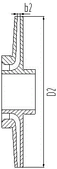
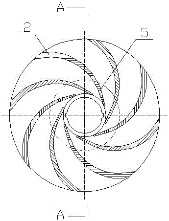
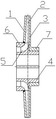
[0030] Example: see figure 2 — Figure 7 , a low specific speed impeller structure, including an impeller body and an impeller root. The impeller body includes a front cover 1 , a blade body 2 and a rear cover 3 , and the front cover 1 , the blade body 2 and the rear cover 3 are integrally formed. The impeller root includes a hub 4, a blade root 5 and a seal ring 6, the blade root 5 is located at the front of the hub 4, the seal ring 6 is sleeved outside the blade root 5, and the hub 4, blade root 5 And the sealing ring part 6 is integrally formed. The principle of cutting the impeller root and the impeller body is: the blade root 5 is an arc segment, and the blade body 2 is a straight line; The diameters are consistent, and the diameter of the inner hole of the rear cover plate 3 is smaller than the diameter of the circle where the inner end of the blade body 2 is located.

[0031] The middle part of the rear cover 3 protrudes backward to form a sleeve 7, the rear cover ...


PUM


Abstract

The invention discloses a low-specific-speed impeller structure and a machining method thereof. The structure comprises an impeller body part and an impeller root part; the impeller body part includes a front cover plate, a blade body part and a back cover plate; the impeller root part includes a hub, a blade root part and a sealing ring part; the middle part of the back cover plate is downwards projected to form a sleeve; the back cover plate coats the back part of the hub through the sleeve; the front cover plate coats the sealing ring part; an annular welding line is formed between the front cover plate and the sealing ring part; and the front cover plate and the sealing ring part are tightly welded through the annular welding line. The machining method comprises the following steps: 1) the impeller body part and the impeller root part are respectively cast; 2) the impeller body part coats the impeller root part from the back end of the impeller root part; and the front cover plate coats the sealing ring part; and 3) the annular welding line between the front cover plate and the sealing ring part is tightly welded. The structure is low in machining difficulty, high in machining precision and better in total quality, improves the machining yield, is high in impeller stability, and can effectively improve the guide efficiency.

Description

technical field [0001] The invention relates to the field of centrifugal pump impeller manufacturing, in particular to an ultra-low specific speed impeller structure and a processing method thereof. Background technique [0002] With the improvement of energy saving, environmental protection and safety requirements, more and more centrifugal pumps with low specific speed are used, and when the specific speed of the impeller is lower than 35, such as figure 1 For the impeller shown, when the ratio of D2 (impeller outer diameter) to b2 (flow channel outlet width) is greater than 30, the current casting technology of this type of closed impeller is difficult to ensure the dimensional accuracy and surface finish of the flow channel, and the scrap rate is very high. High (generally only about 20% pass rate can be achieved), and even cannot be cast, which limits the further development of ultra-low specific speed centrifugal pumps. [0003] Currently, such impellers are manufactu...

Claims


Application Information

Patent Timeline
Patent Type & Authority Applications(China)
IPC IPC(8): F04D29/22F04D29/24B23K33/00
CPCB23K33/00F04D29/2233F04D29/24
Inventor 王天周王运吕见江
Owner 重庆水泵厂有限责任公司
Why Eureka
Try Eureka