
Hydraulic system for torque test worktable and control method of hydraulic system

A technology of hydraulic system and workbench, which is applied in the directions of fluid pressure actuation system components, force/torque/work measuring instruments, fluid pressure actuation devices, etc., can solve the problem of not finding the hydraulic control system of the torque test workbench, etc.

Active Publication Date: 2016-11-16
TAIER HEAVY IND
View PDF6 Cites 9 Cited by
  • Summary
  • Abstract
  • Description
  • Claims
  • Application Information

AI Technical Summary

Problems solved by technology

The hydraulic control system of the torque test bench has not yet been found

Method used


Image

  • Hydraulic system for torque test worktable and control method of hydraulic system
  • Hydraulic system for torque test worktable and control method of hydraulic system

Examples


Embodiment 1

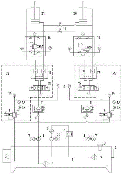
[0016] The present invention is a hydraulic system for a torque experiment workbench, which comprises a fuel tank 1 and two hydraulic oil circuits for controlling the movement of hydraulic cylinders;

Embodiment 2

[0018] Each hydraulic oil circuit includes oil suction filter 4, oil pump motor 7, variable displacement plunger pump 8, check valve 10, high pressure filter 11, pressure switch 12, pressure gauge 13, pressure sensor 14, accumulator 16, by Proportional overflow valve 9, proportional reversing valve 15, hydraulic control check valve 17, integrated valve group composed of oil circuit valve block 23, safety protection valve group 18, and a hydraulic cylinder; oil suction filter 4 is placed in oil tank 1, Oil suction filter 4, variable displacement plunger pump 8, check valve 10, high pressure filter 11, integrated valve group, safety protection valve group 18, and hydraulic cylinder are connected in series in sequence; variable displacement plunger pump 8 is connected to the output shaft of oil pump motor 7; The pressure switch 12, the pressure sensor 14, and the accumulator 16 are respectively connected to the pressure pipeline of the oil circuit valve block 23, and the pressure ...

Embodiment 3

[0020] The rod chamber oil circuit of the tension hydraulic cylinder 20 is connected with the rodless chamber oil circuit of the thrust hydraulic cylinder 21; the rod chamber oil circuit of the tension hydraulic cylinder 20 is connected with the rod chamber oil circuit of the thrust hydraulic cylinder 21; The on and off of the road are all controlled by the electronically controlled one-way valve 19.


PUM


Abstract

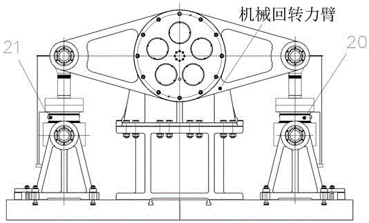
The invention discloses a hydraulic system for a torque test worktable and a control method of the hydraulic system. The hydraulic system comprises an oil tank and two hydraulic oil circuits for controlling the movement of hydraulic cylinders; both of the two hydraulic oil circuits for controlling the movement of the hydraulic cylinders are connected with the oil tank, wherein each hydraulic oil circuit comprises an oil absorption filter, an oil pump motor, a variable displacement piston pump, a one-way valve, a high pressure filter, a pressure switch, a pressure gauge, a pressure sensor, an energy accumulator, an integrated valve group, a safety protection valve group and one of the hydraulic cylinders, and the integrated valve group is composed of a proportional overflow valve, a proportional directional valve, a hydraulic control one-way valve and an oil circuit valve block; the oil absorption filter is placed in the oil tank; and the oil absorption filter, the variable displacement piston pump, the one-way valve, the high pressure filter, the integrated valve group, the safety protection valve group and the hydraulic cylinder are sequentially connected in series. According to the hydraulic system, an acting force of each hydraulic cylinder is applied to two ends of a mechanical rotating moment arm by virtue of a pull force (a thrust force) to form a torque required by a test, so that the test requirement is met.

Description

technical field [0001] The invention relates to a hydraulic system for a torque experiment workbench and a control method thereof. Background technique [0002] With the full development and utilization of hydraulic components and functional modules, hydraulic systems have been widely used in the field of industrial production. With the combined development of computer control technology, sensor measurement and control technology and hydraulic technology, the hydraulic system is also developing towards intelligence, networking and informationization. As a test tool for testing power transmission equipment, the torque test bench has gradually been accepted by everyone. The hydraulic control system of the torque experiment workbench has not been found yet. Contents of the invention [0003] The problem to be solved by the present invention is to provide a hydraulic system for the torque experiment workbench, the hydraulic system applies the force of the tension (thrust) hy...

Claims


Application Information

Patent Timeline
IPC IPC(8): F15B11/16F15B13/06F15B21/02G01L5/00
CPCF15B11/16F15B13/06F15B21/02G01L5/00
Inventor 张德智谢德军江长娟李美杰
Owner TAIER HEAVY IND
Learn More