Transformer substation inspection robot holder control method based on visual servo

A patrol inspection robot and visual servo technology, applied in the direction of non-electric variable control, attitude control, control/adjustment system, etc., can solve the problems of inspection collection image deviation, equipment area deviation, short movement distance, etc., to save labor Effects of labor resources, ensuring safe operation, and improving accuracy

Active Publication Date: 2016-11-16
STATE GRID INTELLIGENCE TECH CO LTD
View PDF7 Cites 59 Cited by
  • Summary
  • Abstract
  • Description
  • Claims
  • Application Information

AI Technical Summary

Problems solved by technology

[0004] (1) The image of the equipment template is captured by the background operator manually controlling the robot pan/tilt and the camera. Generally, the equipment area to be observed is located in the central part of the image, and the parameters related to the pan/tilt angle and the camera focal length are saved accordingly. When the robot performs inspection tasks, no operator interferes with it. After the robot travels to the preset position of each equipment observation, it calls the shooting parameters of the template image of the equipment, performs pan-tilt rotation control and camera focus, and collects real-time data autonomously. The device status image lacks verification of whether the device area deviates from the field of view of the image
[0005] (2) The road on which the robot drives in the substation is basically paved with asphalt or cement, which seems to be smooth, but it is inevitable that there will be some bumps for the driving wheel with a diameter of only 25 cm, which leads to walking all the way during the inspection process. When parking at the preset position, the heading angle of the robot will be different from that of the template image acquisition. This difference leads to the fact that even if the robot accur

Method used


Image

  • Transformer substation inspection robot holder control method based on visual servo
  • Transformer substation inspection robot holder control method based on visual servo
  • Transformer substation inspection robot holder control method based on visual servo

Examples


Example Embodiment

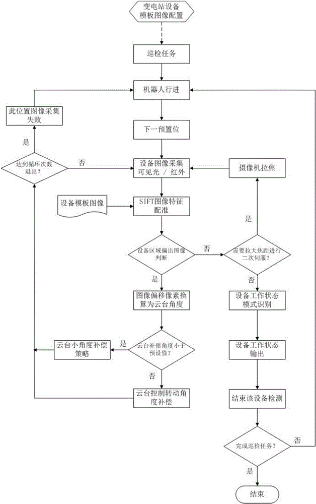
[0058] The present invention will be further limited in combination with the drawings and specific embodiments.

[0059] A visual servo-based substation inspection robot pan-tilt control method. First, the configuration of the inspection robot includes the need to save the equipment images of each preset position of the substation taken by the robot to the template library, and the equipment area to be inspected It is presented in the center of the image with an appropriate size, and the equipment area to be detected is manually calibrated in the template image. The equipment image in the template library corresponds to the equipment position of the substation. When assigning inspection tasks to the robot, it is necessary to clearly point out the various parameters of the template image taken at each preset parking space (such as pan-tilt angle, camera focal length, etc.), and the inspection robot travels to this preset parking space After that, the posture adjustment is performe...


PUM


Abstract

The invention discloses a transformer substation inspection robot holder control method based on visual servo. The transformer substation inspection robot holder control method comprises the steps of: saving equipment images of each preset position of a transformer substation shot by a transformer substation inspection robot into a template library; acquiring the equipment images at the preset positions, and uploading the equipment images to a background service center; invoking the equipment images in the template library by means of the background service center, adopting an SIFT algorithm for matching a real-time inspection image with a template image, and registering common feature points of the two images; acquiring position information of an equipment region in the acquired image; verifying whether the acquired image contains a complete equipment region to be detected, and counting times of visual servo; and subjecting an equipment image acquired at the preset position by the inspection robot the last time to pattern recognition processing, and outputting real-time operating state of the equipment. The transformer substation inspection robot holder control method based on visual servo allows the robot to observe operating state details of the power equipment at far distance and long focal length, and realizes the purpose that the inspection robot observes the transformer substation equipment in a full-coverage manner.

Description

technical field [0001] The invention relates to the technical field of inspection robots for substation equipment, in particular to a control method for a pan-tilt of an inspection robot for substations based on visual servoing. Background technique [0002] Substation equipment inspection robot is an outdoor all-weather mobile platform based on autonomous navigation, precise positioning, and automatic charging, integrating visible light, infrared, sound and other sensors; based on magnetic trajectory and specially arranged RFID tags on the road surface, the optimal path planning of the inspection robot is realized and two-way walking, the video, sound and infrared temperature measurement data of the detected equipment are transmitted to the monitoring room through the wireless network; the inspection background system realizes Discrimination of equipment thermal defects, opening and closing status, and abnormal appearance, as well as instrument readings and oil level gauge ...

Claims


Application Information

Patent Timeline
IPC IPC(8): G05D1/08H04N5/232
CPCG05D1/0891H04N23/67
Inventor 房桦隋吉超傅崇光韩磊任杰张斌李健杨国庆孙志周
Owner STATE GRID INTELLIGENCE TECH CO LTD
Why Eureka
Try Eureka