Structure and preparation method of a flexible perovskite battery

A perovskite and battery technology, applied in the field of solar cells, can solve the problems of reducing bottom electrode resistance, poor heat resistance of flexible substrates, etc., to achieve the effects of reducing series resistance, increasing light absorption, and low resistance

Active Publication Date: 2019-05-14
HUAZHONG UNIV OF SCI & TECH
View PDF6 Cites 0 Cited by
  • Summary
  • Abstract
  • Description
  • Claims
  • Application Information

AI Technical Summary

Problems solved by technology

[0005] Aiming at the above defects or improvement needs of the prior art, the present invention provides a structure of a flexible perovskite solar cell, the purpose of which is to replace the traditional ITO with poor conductivity by using a metal with high conductivity as the bottom electrode, so as to reduce the The small bottom electrode resistance makes it have the potential to prepare large-area devices; the invention also solves the problem of poor heat resistance of flexible substrates by using a doped electron collection layer that does not require high-temperature heating to collect electrons

Method used


Image

  • Structure and preparation method of a flexible perovskite battery
  • Structure and preparation method of a flexible perovskite battery
  • Structure and preparation method of a flexible perovskite battery

Examples


Embodiment 1

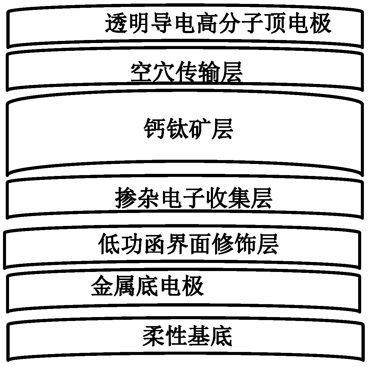
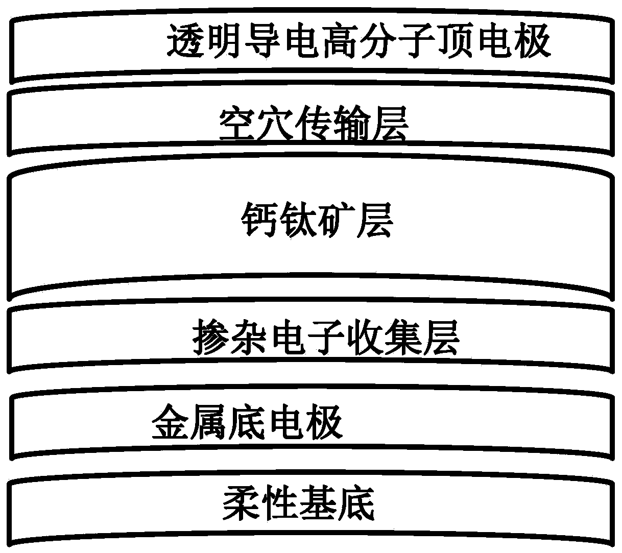
[0035] according to figure 1 structure, the preparation method of the flexible perovskite solar cell described in the present invention is as follows:

[0036] (1) Preparation of the bottom electrode: Deposit a layer of 70nm Ag electrode on a clean flexible substrate by thermal evaporation as the bottom electrode;

[0037] (2) Preparation of a low work function interface modification layer: a layer of PEIE with a thickness of 10 nm was obtained on a flexible substrate by spin coating, soaking, or spraying, and dried at 100 ° C for 10 min;

[0038] (3) Preparation of the doped electron collection layer: a layer of n-doped PCBM with a thickness of 70 nm was obtained on the PEIE by spin coating, soaking, and spraying, and dried at 80 ° C for 5 min;

[0039] (4) Preparation of perovskite light-absorbing layer: the perovskite light-absorbing layer was prepared on n-doped PCBM by anti-solvent method, and dried at 100°C for 10 minutes to obtain a perovskite layer with a thickness of...

Embodiment 2

[0044] according to figure 1structure, the preparation method of the flexible perovskite solar cell described in the present invention is as follows:

[0045] (1) Preparation of the bottom electrode: Deposit a layer of 50nm Ag electrode on a clean flexible substrate by thermal evaporation as the bottom electrode;

[0046] (2) Preparation of a low work function interface modification layer: A layer of PEIE with a thickness of 5 nm was obtained on a flexible substrate by spin coating, soaking, or spraying, and dried at 70°C for 10 min;

[0047] (3) Preparation of the doped electron collection layer: a layer of n-doped PCBM with a thickness of 50 nm was obtained on the PEIE by spin coating, soaking, and spraying, and dried at 80 ° C for 10 min;

[0048] (4) Preparation of perovskite light-absorbing layer: The perovskite light-absorbing layer was prepared on n-doped PCBM by anti-solvent method, and dried at 90°C for 10 minutes to obtain a perovskite layer with a thickness of abou...

Embodiment 3

[0052] according to figure 1 structure, the preparation method of the flexible perovskite solar cell described in the present invention is as follows:

[0053] (1) Preparation of the bottom electrode: Deposit a layer of 100nm Ag electrode on a clean flexible substrate by thermal evaporation as the bottom electrode;

[0054] (2) Preparation of a low work function interface modification layer: A layer of PEIE with a thickness of 15 nm was obtained on a flexible substrate by spin coating, soaking, or spraying, and dried at 100 ° C for 5 min;

[0055] (3) Preparation of the doped electron collection layer: a layer of n-doped PCBM with a thickness of 80 nm was obtained on the PEIE by spin coating, soaking, and spraying, and dried at 100 ° C for 5 min;

[0056] (4) Preparation of perovskite light-absorbing layer: The perovskite light-absorbing layer was prepared on n-doped PCBM by anti-solvent method, and dried at 110°C for 5 minutes to obtain a perovskite layer with a thickness of...


PUM


Abstract

The invention discloses a structure of a flexible perovskite solar cell and a preparation method thereof. The solar cell structure proposed by the present invention is composed of a flexible substrate, a metal bottom electrode, a doped electron collection layer, a perovskite layer, a hole transport layer and a transparent conductive polymer top electrode, in order from bottom to top. The battery structure proposed by the present invention can use a low work function interface modification layer and a doped electron collection layer as the cathode modification layer to avoid the use of metal oxides, making low-temperature preparation possible. Using metal as the bottom electrode, the resistance value is much smaller than that of common ITO, which can reflect light and can be used in the production of large-area batteries. The battery structure of the present invention can be applied to power generation devices that cannot use rigid materials such as curved walls and car tops, and can be bent without affecting device performance. It has broad application prospects for realizing flexible large-area perovskite batteries.

Description

technical field [0001] The invention belongs to the field of solar cells, and more specifically relates to a structure of a flexible perovskite solar cell. Background technique [0002] With the deteriorating global climate and the continuous consumption of non-renewable energy, it is imminent for people to utilize clean and renewable energy. Solar energy has attracted much attention due to its advantages of cleanness, large reserves, and wide distribution. In the utilization of solar energy, solar cells account for a large proportion. In recent years, perovskite cells have become a research hotspot due to their advantages of simple preparation technology, low cost, and high conversion efficiency. [0003] The currently researched perovskite batteries are mainly deposited on conductive glass (FTO, ITO). Due to the fragility of glass, the application of perovskite batteries is greatly limited. With the gradual development of wearable electronic devices, the research and de...

Claims


Application Information

Patent Timeline
Patent Type & Authority Patents(China)
IPC IPC(8): H01L51/42H01L51/44
CPCH10K30/00H10K30/82Y02E10/549
Inventor 周印华覃飞童金辉葛茹毛霖李在房
Owner HUAZHONG UNIV OF SCI & TECH
Why Eureka
Try Eureka