Eureka AIR delivers breakthrough ideas for toughest innovation challenges, trusted by R&D personnel around the world.

Integrated chassis filter plate structure

A filter board and integrated technology, applied in the field of filters, can solve the problems of wires occupying the internal space of customer equipment, less available space for equipment, inconvenient update and disassembly, etc., to avoid electromagnetic interference and physical damage, save space, and be less prone to errors Effect

Active Publication Date: 2016-11-16
CHONGQING DAJI ELECTRONICS TECH
View PDF6 Cites 3 Cited by
  • Summary
  • Abstract
  • Description
  • Claims
  • Application Information

AI Technical Summary

Problems solved by technology

Since the line filter needs to be installed on other equipment to realize its filtering function during use, in the existing connection method between the filter and other equipment, the connection method generally adopts wire welding for connection processing. However, due to customer The internal space of the equipment is extremely narrow and there are many internal interconnection wires in the customer equipment. Using wire welding to connect will not only cause a large welding workload, too many solder joints, and error-prone, but also very inconvenient to update and disassemble. At the same time, too many wires will occupy The internal space of the customer's device, resulting in less available space inside the device

Method used


Image

  • Integrated chassis filter plate structure
  • Integrated chassis filter plate structure
  • Integrated chassis filter plate structure

Examples


Embodiment Construction

[0018] The technical solutions in the present invention will be further described below in conjunction with the accompanying drawings and embodiments.

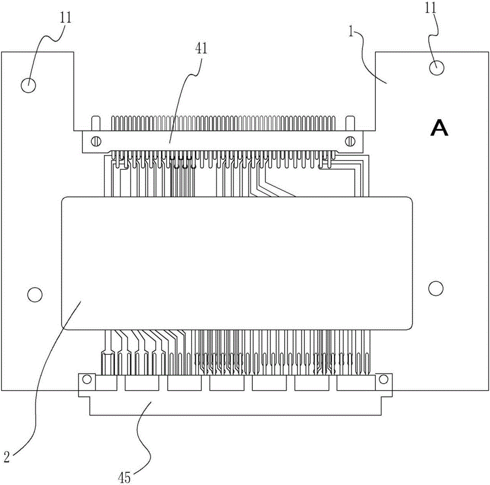
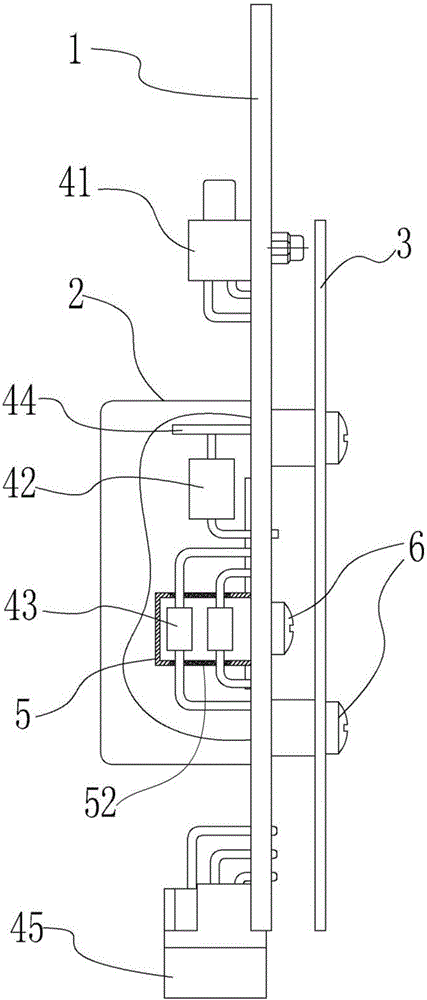
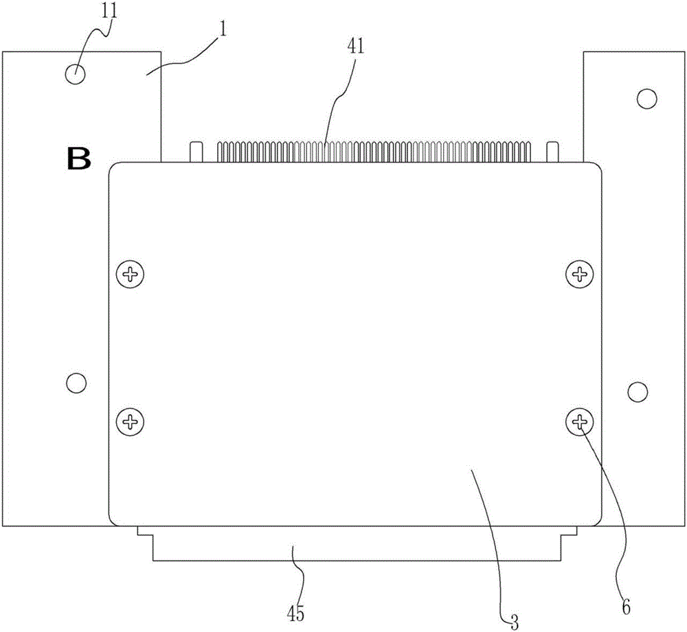
[0019] As shown in the figure, the present invention proposes an integrated chassis filter board structure, including a PCB substrate 1, a shield cover 2, a protective plate 3, a filter, and an installation box 5, wherein the PCB substrate 1 is provided with several installation screws. A hole 11 and a fixing column 12, the fixing column 12 is provided with a fixing screw hole, and the fixing screw hole communicates with two opposite sides of the PCB substrate 1;

[0020] The shielding cover 2 and the protective plate 3 are all fixed on the PCB substrate 1 by screws 6 and fixing screw holes, and the shielding cover 2 and the protective plate 3 are respectively located on two opposite sides of the PCB substrate 1, so that the PCB substrate 1 Electromagnetic protection and physical protection are carried out on the electronic co...


PUM


Abstract

The invention provides an integrated chassis filter plate structure, comprising a PCB (Printed Circuit Board) substrate, a screen, a protective plate and a filter, wherein the PCB substrate is provided with mounting holes and a fixed column; the screen and the protective plate are fixed on the PCB substrate and located on two opposite sides of the PCB substrate respectively, the screen is installed on the PCB substrate in an inverted mode, and the protective plate is located at the top of the fixed column and is parallel to the PCB substrate; the filter comprises an input connector, a two-way TVS (Transient Voltage Suppressor) diode, a capacitor, an earth plate and an output connector which are integrated on the PCB substrate and located on the same side as the screen, the input connector and the output connector are rectangular connectors and are located at the edge of the PCB substrate, the two-way TVS diode, the capacitor and the earth plate are located within a cavity encircled by the screen and the PCB substrate, one end of the two-way TVS diode is welded on the PCB substrate, and the other end of the two-way TVS diode is connected with the earth plate. The integrated chassis filter plate structure realizes modularized installation of the filter, reduces the assembly difficulty, improves the installation efficiency, and is more convenient to detach and replace.

Description

technical field [0001] The invention relates to the field of filters, in particular to an integrated chassis filter board structure. Background technique [0002] The filter is a filter circuit composed of components such as capacitors, inductors and resistors. It can effectively filter out the frequency points of a specific frequency in the power line or frequencies other than this frequency point to obtain a power signal of a specific frequency, or eliminate Power signal after a specific frequency. Since the line filter needs to be installed on other equipment to realize its filtering function during use, in the existing connection method between the filter and other equipment, the connection method generally adopts wire welding for connection processing. However, due to customer The internal space of the equipment is extremely narrow and there are many internal interconnection wires in the customer equipment. Using wire welding to connect will not only cause a large weld...

Claims


Application Information

Patent Timeline
IPC IPC(8): H01R12/71H01R13/6594H03H7/01
CPCH01R12/712H01R13/6594H03H7/01
Inventor 耿利群何天成董俊峰黄记堂肖瑶
Owner CHONGQING DAJI ELECTRONICS TECH
Why Eureka
Eureka Blog
Learn More