
Assembly type steel plate combined beam bridge based on reinforced concrete combined bridge deck slab and construction method of assembly type steel plate combined beam bridge

A combined bridge and prefabricated technology, applied in the direction of erecting/assembling bridges, bridges, bridge parts, etc., can solve the problems of too large spacing between main beams and short construction period, and achieve the effects of convenient construction, simple steps and reasonable design.

Inactive Publication Date: 2016-11-23
CHANGAN UNIV
View PDF9 Cites 29 Cited by
  • Summary
  • Abstract
  • Description
  • Claims
  • Application Information

AI Technical Summary

Problems solved by technology

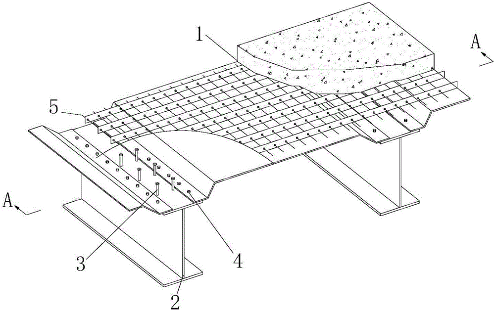
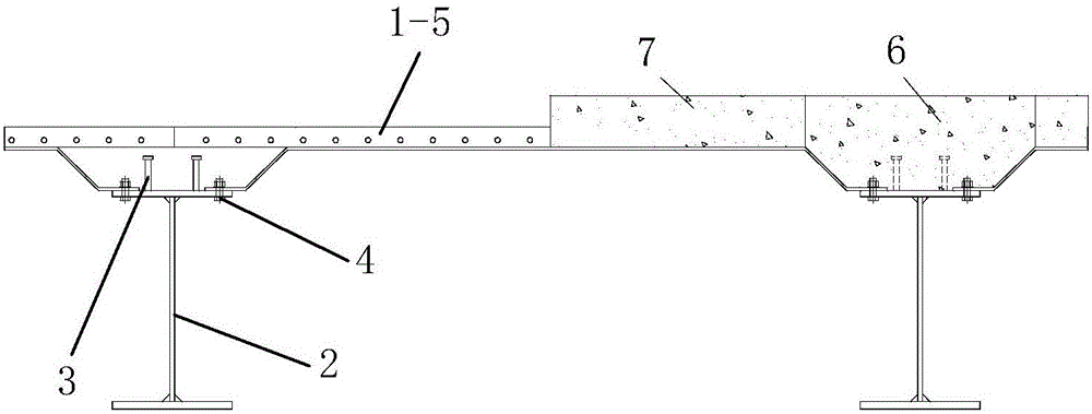
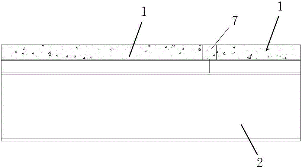
[0004] The technical problem to be solved by the present invention is to provide an assembled steel plate composite girder bridge based on steel-concrete composite bridge deck, which has simple structure, reasonable design, easy construction, good use effect and excellent mechanical properties in view of the deficiencies in the prior art. Excellent, fast installation and disassembly construction, short construction period, and can effectively solve the problem of excessive main beam spacing

Method used


Image

  • Assembly type steel plate combined beam bridge based on reinforced concrete combined bridge deck slab and construction method of assembly type steel plate combined beam bridge
  • Assembly type steel plate combined beam bridge based on reinforced concrete combined bridge deck slab and construction method of assembly type steel plate combined beam bridge
  • Assembly type steel plate combined beam bridge based on reinforced concrete combined bridge deck slab and construction method of assembly type steel plate combined beam bridge

Examples


Embodiment Construction

[0055] Such as figure 1 , figure 2 and image 3 The fabricated steel plate composite girder bridge based on the steel-concrete composite bridge deck shown includes a main girder support structure composed of multiple steel girders arranged on the same horizontal plane and multiple steel girders installed from front to rear For the steel-concrete composite bridge deck segment on the supporting structure, the multiple steel girders are I-shaped steel girders arranged along the longitudinal direction of the bridge, and each steel girder is spliced ​​by multiple steel girder segments 2 A plurality of said steel girder sections 2 are arranged on the same horizontal plane from back to front along the longitudinal bridge direction; multiple said steel-concrete composite bridge deck sections have the same structure and are arranged from rear to front along the longitudinal bridge direction. The front is arranged on the same level; each of the steel-concrete composite bridge deck se...


PUM


Abstract

The invention discloses an assembly type steel plate combined beam bridge based on a reinforced concrete combined bridge deck slab and a construction method of assembly type steel plate combined beam bridge. The steel plate combined beam bridge comprises a main beam supporting structure composed of multiple main steel beams, and multiple reinforced concrete combined bridge deck slab sections installed on the main beam supporting structure from front to back, wherein the multiple main steel beams are I-beam main beams distributed in the longitudinal bridge direction. The reinforced concrete combined bridge deck slab sections comprise multiple reinforced concrete combined bridge deck slab units distributed from left to right. Longitudinal cast-in-place concrete structures are evenly distributed over the main steel beams. The construction method includes the steps of firstly, bridge lower portion supporting structure construction, secondly, main steel beam erection construction, thirdly, reinforced concrete combined bridge deck slab section installation, fourthly, longitudinal connecting reinforcing steel bar penetration, and fifthly, longitudinal cast-in-place concrete structure pouring construction. The assembly type steel plate combined beam bridge is reasonable in design, easy and convenient to construct, good in use effect, excellent in mechanical performance, high in installing and detaching construction speed, short in construction period and capable of effectively solving the problem that the main beam interval is too large.

Description

technical field [0001] The invention belongs to the technical field of bridge construction, and in particular relates to an assembled steel plate composite girder bridge based on a steel-concrete composite bridge deck and a construction method thereof. Background technique [0002] Steel plate composite girder bridges are composed of steel girders, concrete bridge decks and connecting systems. For bridge decks with a large width, it is usually connected in the form of longitudinal wet joints. At the wet joints, it is necessary to build formwork, connect reserved steel bars, and pour wet joint concrete. This construction method has complicated procedures and requires on-site operations. The amount is large, and it is not convenient for secondary replacement of the bridge deck. [0003] The rapid assembly construction of steel plate composite girder bridges is a construction method that develops relatively rapidly at home and abroad. It is widely used in rapid construction of...

Claims


Application Information

Patent Timeline
IPC IPC(8): E01D2/00E01D19/12E01D21/00
CPCE01D2/00E01D19/125E01D21/00E01D2101/268
Inventor 刘永健王莉莉高诣民张泽军
Owner CHANGAN UNIV
Learn More