Vertical efficient water-cooling condenser

A water-cooled, condenser technology, used in evaporators/condensers, refrigerators, refrigeration components, etc., can solve the problem that the heat exchange efficiency of the condenser is not very high, so as to improve the heat exchange efficiency, increase the contact area, improve the The effect of outflow efficiency

Pending Publication Date: 2016-11-23
成都馨迪璐莎科技有限公司
View PDF0 Cites 1 Cited by
  • Summary
  • Abstract
  • Description
  • Claims
  • Application Information

AI Technical Summary

Problems solved by technology

The heat exchange efficiency of the condenser in the prior art is not very high, in order to meet the production requirements, a condenser with better heat exchange efficiency is needed to solve the above problems

Method used


Image

  • Vertical efficient water-cooling condenser
  • Vertical efficient water-cooling condenser

Examples


Embodiment 1

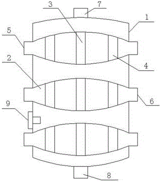
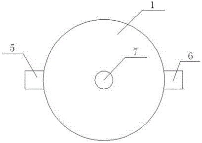
[0017] A vertical high-efficiency water-cooled condenser with the advantages of high heat exchange efficiency, such as figure 1 , figure 2 As shown, it is specially arranged as the following structure: including a barrel body 1, a plurality of cooling water tanks 2 arranged in the barrel body 1 sequentially from top to bottom; The water tank 2 is provided with a through hole, and the two ends of the cooling water tank 2 are respectively connected with a cooling water inlet pipe 5 and a cooling water outlet pipe 6; Condensed water outlet pipe 8; the side wall of the barrel body 1 is provided with a temperature monitor 9, and the temperature monitor 9 includes a temperature display arranged on the outer wall of the barrel body 1 and a temperature sensor arranged on the inner wall of the barrel body 1. The cooling water tank 2 is a box whose middle height is higher than that of the surroundings, so that the hot air can be guided to flow around the cooling water tank, the contac...

Embodiment 2

[0019] This embodiment is further optimized on the basis of the above-mentioned embodiments, further to better realize the present invention, such as figure 1 As shown, the following arrangement structure is adopted in particular: a plurality of uniformly distributed first through-holes 3 and second through-holes 4 are respectively opened in the middle and around the box body 1, and the diameter of the first through-hole 3 is smaller than that of the second through-hole. The pipe diameter of the through hole 4. Furthermore, the volumes of the first through hole 3 and the second through hole 4 are equal to the volume of the hot gas intake pipe 7 .

Embodiment 3

[0021] This embodiment is further optimized on the basis of any of the above embodiments, further to better realize the present invention, such as figure 1 As shown, the following arrangement structure is adopted in particular: the bottom of the barrel body 1 is a curved thin plate whose middle part is lower than the surrounding; the design of the curved surface can facilitate the accumulation of condensed water, and facilitate the flow of condensed water out of the box body 1 through the condensed water outlet pipe 8 outside.


PUM


Abstract

The invention discloses a vertical efficient water-cooling condenser. The vertical efficient water-cooling condenser comprises a bucket body and a plurality of cooling water tanks sequentially arranged in the bucket body from top to bottom. Each cooling water tank is a tank body with the middle portion being higher than the periphery. Through holes are formed in the cooling water tanks correspondingly. The two ends of each cooling water tank communicate with a cooling water inlet pipe and a cooling water outlet pipe correspondingly. The top of the bucket body communicates with a hot air inlet pipe. The bottom of the bucket body communicates with a condensate water outlet pipe. A temperature monitor is arranged on the side wall of the bucket body and comprises a temperature displayer arranged on the outer wall of the bucket body and a temperature sensor arranged on the inner wall of the bucket body. A plurality of evenly-distributed first through holes are formed in the middle portions of the tank bodies, and a plurality of evenly-distributed second through holes are formed in the peripheries of the tank bodies. The diameter of the first through holes is smaller than the diameter of the second through holes. The bottom of the bucket body is an arc-surface sheet with the middle portion being lower than the periphery. The diameter of the hot air inlet pipe is larger than the diameter of the condensate water outlet pipe. Compared with the prior art, the vertical efficient water-cooling condenser has the advantage of being high in heat exchange efficiency.

Description

technical field [0001] The invention relates to the field of condensing equipment, in particular to a vertical high-efficiency water-cooled condenser. Background technique [0002] The condenser is a component of the refrigeration system, which is a kind of heat exchanger, which can convert gas or vapor into liquid, and transfer the heat in it to the air near the pipe in a very fast way; the working process of the condenser is a Exothermic process, so the condenser temperature is higher. [0003] Power plants use many condensers to condense the exhaust steam from the turbines. Condensers are used in refrigeration plants to condense refrigerant vapors such as ammonia and freon. Condensers are used in the petrochemical industry to condense hydrocarbons and other chemical vapors. In the distillation process, the device that converts vapor into liquid state is also called condenser. All condensers operate by removing heat from a gas or vapor. The heat exchange efficiency of...

Claims


Application Information

Patent Timeline
Patent Type & Authority Applications(China)
IPC IPC(8): F25B39/04
CPCF25B39/04F25B2339/047
Inventor 王志国
Owner 成都馨迪璐莎科技有限公司
Why Eureka
Try Eureka