
A simple and convenient detection apparatus for collecting lens surface types and a detection method based on the apparatus

A detection device and lens technology, applied in the direction of measuring devices, optical devices, instruments, etc., can solve the problem that the inner surface shape of large-diameter collection lenses cannot be detected, etc., and achieve the effect of easy detection method, simple device, and simple steps

Inactive Publication Date: 2016-11-23
HARBIN INST OF TECH
View PDF8 Cites 0 Cited by
  • Summary
  • Abstract
  • Description
  • Claims
  • Application Information

AI Technical Summary

Problems solved by technology

[0006] The purpose of the present invention is to solve the problem that the existing detection device cannot detect the inner surface shape of the large-diameter collection lens with a relatively long axial length, thereby providing a simple detection device for the surface shape of the collection lens and a detection method based on the device

Method used

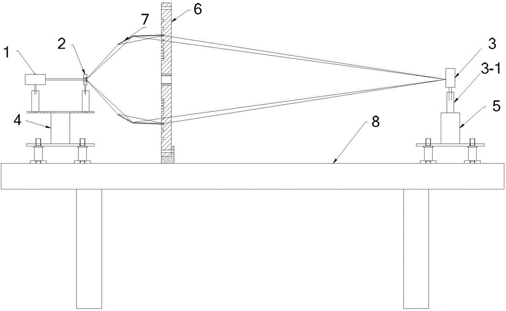
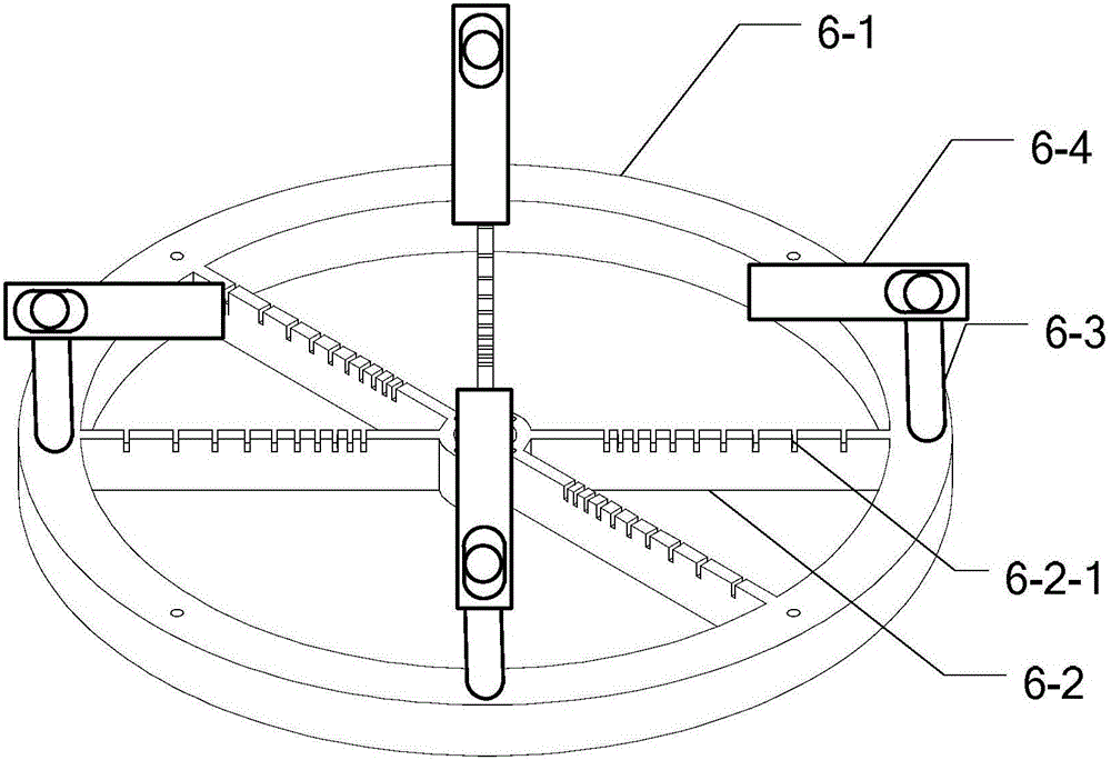

Image

  • A simple and convenient detection apparatus for collecting lens surface types and a detection method based on the apparatus
  • A simple and convenient detection apparatus for collecting lens surface types and a detection method based on the apparatus
  • A simple and convenient detection apparatus for collecting lens surface types and a detection method based on the apparatus

Examples


specific Embodiment approach 1

[0024] Specific implementation mode one: combine figure 1 with figure 2 Describe this embodiment in detail, the simple and convenient detection device of collecting lens surface described in this embodiment, comprises semiconductor laser 1, frosted glass 2, CCD sensor 3, the first five-dimensional adjustment table 4, the second five-dimensional adjustment table 5, collecting Lens support 6 and computer;

[0025] A black paper is pasted on the frosted glass 2, and a small round hole is opened on the black paper;

[0026] The laser light emitted by the semiconductor laser 1 is incident on the ground glass 2, and the light transmitted through the small round hole of the ground glass 2 is converged to the CCD sensor 3 through the collecting lens 7;

[0027] The collection lens support 6 fixes the collection lens 7 in the optical path, the semiconductor laser 1 and the frosted glass 2 are fixed on the first five-dimensional adjustment table 4, the CCD sensor 3 is fixed on the se...

specific Embodiment approach 2

[0034] Embodiment 2: This embodiment is a further description of the simple detection device for collecting lens surface shape described in Embodiment 1. In this embodiment, the small round hole is a round hole of Φ3mm.

[0035] The diameter of the capillary is usually Φ3mm, so the small hole is also a round hole of Φ3mm.

specific Embodiment approach 3

[0036] Embodiment 3: This embodiment further describes the simple detection device for collecting lens surface shape described in Embodiment 1 or 2. In this embodiment, the semiconductor laser 1 outputs visible light.

[0037] The semiconductor laser 1 outputs visible light, which facilitates the debugging of the optical path, and red light is suitable for visible light.


PUM


Abstract

A simple and convenient detection apparatus for collecting lens surface types and a detection method based on the apparatus relates to a simple and convenient technique for detecting capillary discharge Z-pinch extreme ultraviolet light source collecting lens surface types, and solves a problems that existing detecting apparatuses can not detect the inner surface type of a large-diameter collecting lens having a relatively long axial length. The laser emitted from a semiconductor laser is incident to ground glass, and the light transmitted through a small round hole of the ground glass is collected by a collecting lens to a CCD sensor. A computer is used for measuring faculae received by the CCD sensor and the recording faculae information. A first five-dimensional adjustment table is adjusted so that an optical axis of the laser emitted by the semiconductor laser coincides with the axis of the small round hole in the ground glass; a collecting lens support member is adjusted so that the axis of the collecting lens coincides with the optical axis; and a second five-dimensional adjustment table and a liftable sleeve are adjusted to make the CCD sensor receive a light beam. According to the facula information obtained by the computer, whether the collecting lens is in accordance with requirements is judged. The invention is applied to detecting the inner surface type of the collecting lens.

Description

technical field [0001] The invention relates to a simple detection technology for the surface shape of a lens collected by a capillary discharge Z pinch extreme ultraviolet light source. Background technique [0002] Capillary discharge Z pinch extreme ultraviolet light source (DPP technology), is to apply a large current and fast pulse to both ends of the ceramic capillary to discharge. At this time, the working medium gas filled in the capillary begins to generate gas ionization along the tube wall, forming The plasma shell, and then under the action of the Lorentz force generated by the internal strong electromagnetic field, the plasma shell moves toward the axis. This process is called Z pinch. At the same time as the pinch, ohmic heating will be generated to generate high-temperature plasma body, and then interact with the gas in the tube to produce ions of higher valence gas, such as Xe gas medium to produce decavalent Xe ions Xe 10+ , when the ion is de-excited, it w...

Claims


Application Information

Patent Timeline
IPC IPC(8): G01B11/24
CPCG01B11/24
Inventor 祝东远赵永蓬徐强
Owner HARBIN INST OF TECH
Learn More