A power diode forward dynamic resistance test device

A power diode and dynamic resistance technology, applied in the field of power diode forward dynamic resistance testing devices, can solve the problems of testing without considering the forward dynamic resistance of power diodes, and achieve automatic detection and display, low mutual interference, and high performance. Effects of Accuracy and Stability

Active Publication Date: 2017-05-17
长春市八八四八科技有限公司
View PDF3 Cites 0 Cited by
  • Summary
  • Abstract
  • Description
  • Claims
  • Application Information

AI Technical Summary

Problems solved by technology

Diode test system based on virtual instrument developed by Ye Feng [Ye Feng, Research on diode test system based on virtual instrument [J], Mechanical Manufacturing, Vol.50, No.4:(2012):66.], divided into upper computer The upper computer provides control digital signals and analog input signals for the lower computer, and receives the analog signals and digital signals fed back by the lower computer. At the same time, the upper computer software provides test results display, test result statistics, and debugging for testers. Calibration and other functional services; the lower computer is directly connected to the test point, and the input analog signal is converted into the excitation voltage or excitation current required by the test through the amplification and filtering of the conditioning circuit; the software program uses LabView from National Instruments (NI) 2009 and NI-DAQmx data acquisition driver, this test system can not only be used for parameter measurement of high-voltage diodes, but also for ordinary diodes, suitable for automatic detection of diodes on the production line, but it does not take into account the forward dynamics of power diodes Resistance Test

Method used


Image

  • A power diode forward dynamic resistance test device
  • A power diode forward dynamic resistance test device
  • A power diode forward dynamic resistance test device

Examples


Embodiment Construction

[0032] In order to make the objectives, technical solutions and advantages of the present invention clearer, the present invention will be further described in detail below with reference to the accompanying drawings.

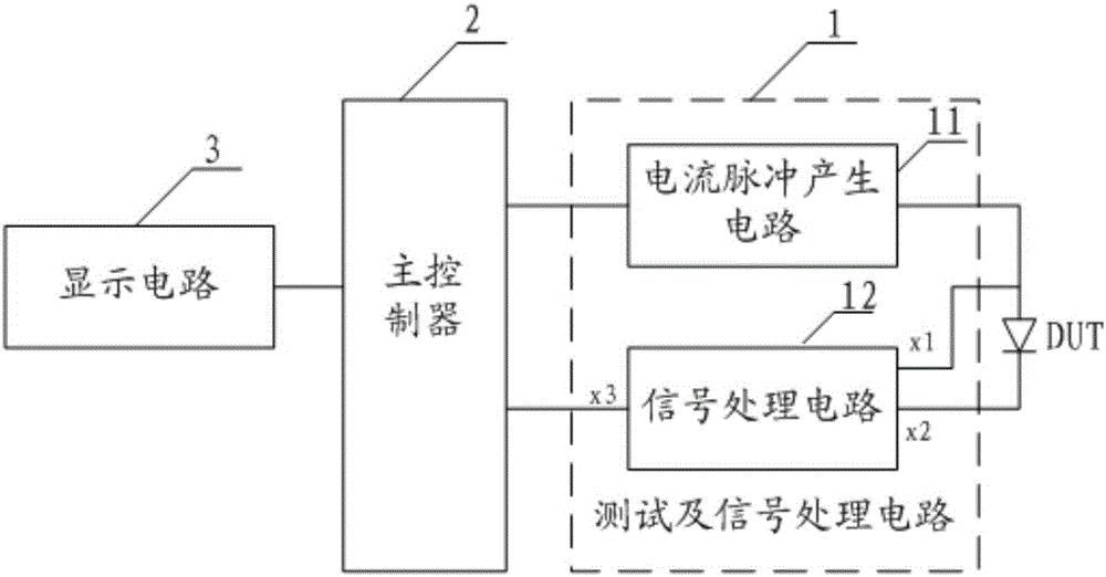
[0033] like Figure 1 to Figure 3 As shown, in the embodiment of the present invention, a power diode forward dynamic resistance test device is provided, including a test and signal processing circuit 1, a display circuit 3, and a main control connected to the test and signal processing circuit and the display circuit 3. device 2; where,

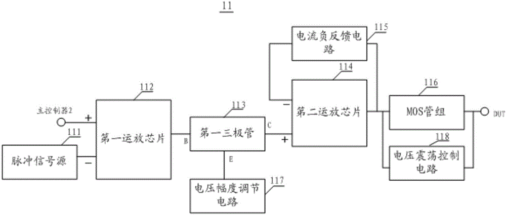
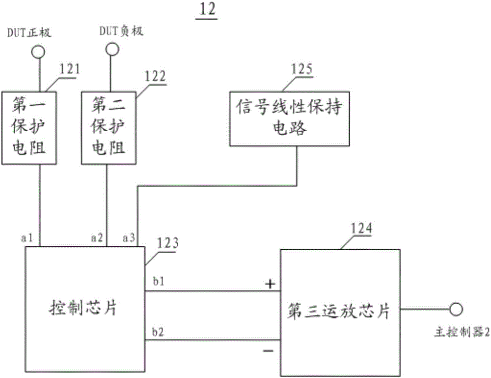
[0034] The test and signal processing circuit 1 includes a current pulse generation circuit 11 for loading a large current pulse signal on the power diode DUT under test and turning it on, and a current pulse generating circuit 11 for acquiring the voltage signal generated after the power diode DUT under test is turned on and connecting it with the power diode DUT. The signal processing circuit 12 for processing the obtained...


PUM


Abstract

The invention provides a forward dynamic resistance testing apparatus for a power diode. The testing apparatus comprises a testing and signal processing circuit, a main controller, and a display circuit. The testing and signal processing circuit includes a current pulse generation circuit for loading a heavy current pulse signal on a tested power diode and realizing conduction of the power diode and a signal processing circuit for obtaining a voltage signal generated after conduction of the tested power diode and processing the obtained voltage signal. The current pulse generation circuit consists of a pulse signal source, a first operational amplifier chip, a first triode, a voltage amplitude adjusting circuit, second operational amplifier chip, a current negative feedback circuit, a voltage oscillation control circuit and an MOS tube group. The main controller connected with the testing and signal processing circuit is used for calculating a processed signal to obtain a forward dynamic resistance value of a tested power diode and sending the forward dynamic resistance value to the display circuit for displaying. The apparatus is simple and practical; automatic detection and displaying of a forward dynamic resistance value of a power diode can be realized; and the time and effort are saved.

Description

technical field [0001] The invention relates to the technical field of power diode testing, in particular to a power diode forward dynamic resistance testing device. Background technique [0002] As a basic component commonly used in circuits such as rectification and voltage stabilization, the core of the diode is a PN junction, which has unidirectional conductivity, and the forward characteristic can be described by the volt-ampere characteristic. When the forward voltage is greater than the barrier voltage of the PN junction, the diode is forward biased, and its forward current increases exponentially with the increase of the forward voltage. [0003] With the continuous development of industry, people have higher and higher requirements for diode performance, especially for power diodes, its forward dynamic resistance test is more and more important and urgent, because the loss of forward dynamic resistance under high current is relatively significant, If this phenomeno...

Claims


Application Information

Patent Timeline
Patent Type & Authority Patents(China)
IPC IPC(8): G01R27/14
CPCG01R27/14
Inventor 韦文生罗飞蔡斌应柯杰
Owner 长春市八八四八科技有限公司
Why Eureka
Try Eureka