
Bonding technology for wafer surface and semiconductor device structure

A bonding process and device structure technology, applied in the direction of semiconductor devices, semiconductor/solid-state device manufacturing, semiconductor/solid-state device components, etc. Problems such as low degree of bond bonding can eliminate abnormal appearance and color, optimize thickness uniformity, and improve performance.

Inactive Publication Date: 2016-11-23
WUHAN XINXIN SEMICON MFG CO LTD
View PDF6 Cites 3 Cited by
  • Summary
  • Abstract
  • Description
  • Claims
  • Application Information

AI Technical Summary

Problems solved by technology

[0002] During the wafer manufacturing process, due to the lack of bonded Si atoms at the substrate Si interface and the existence of unbonded electrons at the interface Si atoms, electrically active dangling bonds are formed at the Si interface (generally, the crystal lattice suddenly terminates at the surface, and the Each atom of the outermost layer will have an unpaired electron, that is, an unsaturated bond is arranged, and this bond is called a dangling bond (Traps for short), and the bonding degree of this dangling bond is relatively low. There are fewer sources of atoms for dangling bonds to form bonds and lack of bonding power, resulting in a lower degree of bonding of dangling bonds between Si interfaces, resulting in Dark Current (dark current), BLC (BlackLight Compensation, backlight compensation function) of semiconductor devices, etc. The performance is poor, and the surface thickness of the semiconductor device is not uniform, resulting in an abnormal phenomenon of uneven color on the surface of the semiconductor device

Method used


Image

  • Bonding technology for wafer surface and semiconductor device structure
  • Bonding technology for wafer surface and semiconductor device structure
  • Bonding technology for wafer surface and semiconductor device structure

Examples


Embodiment Construction

[0035] The bonding process and semiconductor device structure of a wafer surface of the present invention will be described in more detail below in conjunction with flow charts and schematic diagrams, wherein a preferred embodiment of the present invention is represented, and it should be understood that those skilled in the art can modify the description herein the present invention, while still realizing the advantageous effects of the present invention. Therefore, the following description should be understood as the broad knowledge of those skilled in the art, but not as a limitation of the present invention.

[0036] In the following paragraphs the invention is described more specifically by way of example with reference to the accompanying drawings. Advantages and features of the present invention will be apparent from the following description and claims. It should be noted that all the drawings are in a very simplified form and use imprecise scales, and are only used ...


PUM


Abstract

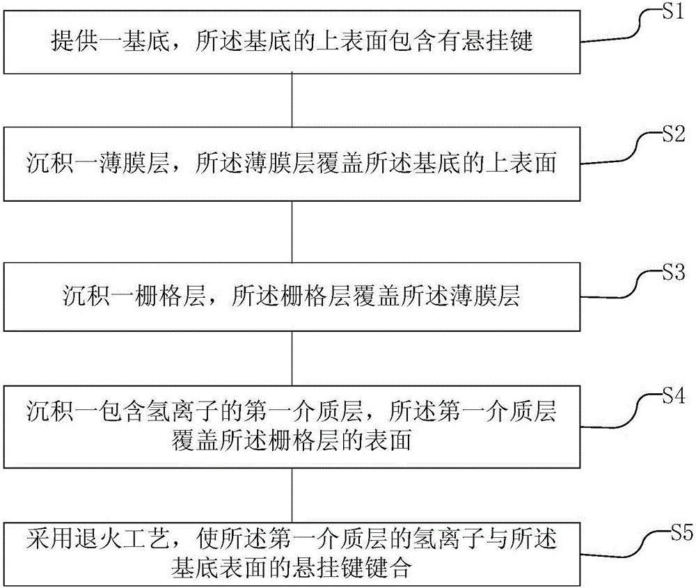
The invention discloses a bonding technology for a wafer surface and a semiconductor device structure. The bonding technology comprises the steps that a substrate is provided, wherein dangling bonds are included on the upper surface of the substrate; a film layer is deposited, wherein the film layer covers the upper surface of the substrate; a grid layer is deposited, wherein the grid layer covers the film layer; a first dielectric layer including hydrogen ions is deposited, wherein the first dielectric layer covers the surface of the grid layer; the annealing technology is adopted, and the hydrogen ions of the first dielectric layer are made to be bonded with the dangling bonds on the surface of the substrate. According to the bonding technology, the first dielectric layer including the hydrogen ions is deposited on the grid layer, bonding of the hydrogen ions of the first dielectric layer and the Si dangling bonds on the wafer surface is promoted, the bonding degree of the dangling bonds of the Si interface of a wafer is improved, and the Dark Current and BLC performance of a semiconductor is remarkably improved.

Description

technical field [0001] The invention relates to the technical field of semiconductor device preparation, in particular to a wafer surface bonding process and a semiconductor device structure. Background technique [0002] During the wafer manufacturing process, due to the lack of bonded Si atoms at the substrate Si interface and the existence of unbonded electrons at the interface Si atoms, electrically active dangling bonds are formed at the Si interface (generally, the crystal lattice suddenly terminates at the surface, and the Each atom of the outermost layer will have an unpaired electron, that is, an unsaturated bond is arranged, and this bond is called a dangling bond (Traps for short), and the bonding degree of this dangling bond is relatively low. There are fewer sources of atoms for dangling bonds to form bonds and lack of bonding power, resulting in a lower degree of bonding of dangling bonds between Si interfaces, resulting in Dark Current (dark current), BLC (Bla...

Claims


Application Information

Patent Timeline
Patent Type & Authority Applications(China)
IPC IPC(8): H01L21/60H01L23/492
CPCH01L23/4924H01L24/83H01L2224/83365H01L2224/83379
Inventor 孙鹏王喜龙胡胜王前文
Owner WUHAN XINXIN SEMICON MFG CO LTD
Learn More