Lithium slurry battery reactor

A slurry battery and reactor technology, applied in the direction of fuel cell additives, regenerative fuel cells, fuel cell components, etc., can solve the problems of increasing, lithium ion consumption, polarization internal resistance, etc., to increase the internal resistance of the battery Effect

Active Publication Date: 2016-11-23
南京竞予能源有限公司
View PDF7 Cites 23 Cited by
  • Summary
  • Abstract
  • Description
  • Claims
  • Application Information

AI Technical Summary

Problems solved by technology

The use of the unipolar diaphragm can increase the cavity height of the positive electrode reaction chamber in the battery reactor and the solid content of the battery slurry at the same time, thereby increasing the energy density of the battery, and at the same time solving the problem of the negative electrode porous collector layer in the bipolar diaphragm structure. Problems of lithium ion consumption and polarization internal resistance increase caused by metallic lithium deposition

Method used


Image

  • Lithium slurry battery reactor
  • Lithium slurry battery reactor

Examples


Embodiment 1

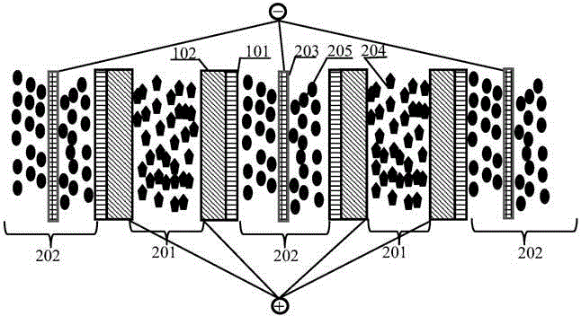
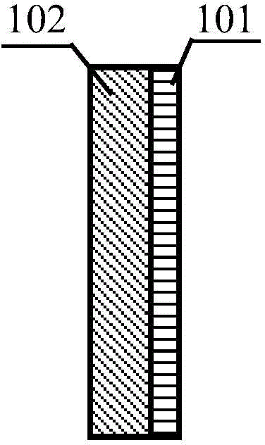
[0026] Such as figure 1 As shown, the unipolar separator includes a positive electrode porous collector layer 102 and a separator layer 101 , wherein the positive electrode porous collector layer 102 is located on one side of the separator layer 101 and is in close contact with the separator layer 101 . In this embodiment, the positive electrode porous collector layer 102 is a 200-mesh stainless steel mesh that can pass through lithium ions with a surface composite conductive carbon black, the isolation layer 101 is a polyethylene porous polymer separator, and the positive electrode porous collector layer 102 and The isolation layer 101 is fixed at the edge by bonding.

[0027]as attached figure 2 As shown, several unipolar separators are stacked sequentially according to the order in which the isolation layer 101 is placed relative to the isolation layer 101, wherein the gap between two adjacent positive electrode porous collector layers 102 constitutes the positive electro...

Embodiment 2

[0030] The structure of the battery reactor is the same as in Example 1. The difference is:

[0031] The unipolar separator in this embodiment is composited by bonding the positive electrode porous current collector layer 102 and the separator layer 101 through edge positions;

[0032] The unipolar separator is compounded with a polyethylene porous membrane with a thickness of 10um on the outside of the isolation layer;

[0033] The positive electrode porous current collector layer 102 is a porous mixture composed of conductive carbon black and a binder, wherein the mass fraction of conductive carbon black is 80%;

[0034] The isolation layer 101 is polypropylene material;

[0035] The negative electrode current collector 203 is carbon fiber conductive cloth;

[0036] The cavity heights of the positive electrode reaction chamber 201 and the negative electrode reaction chamber 202 are both 5mm;

[0037] In this embodiment, the positive electrode slurry 204 is an organic ele...


PUM

PropertyMeasurementUnit
thicknessaaaaaaaaaa
thicknessaaaaaaaaaa
pore sizeaaaaaaaaaa

Abstract

The invention provides a lithium slurry battery reactor. The lithium slurry battery reactor comprises positive pole reaction cavities, negative pole reaction cavities, unipolar diaphragms, negative pole current collectors, positive pole slurry and negative pole slurry, wherein each unipolar diaphragm is formed by an isolating layer and a positive pole porous current collector layer located on a single side of the isolating layer through close contacting, and a plurality of unipolar diaphragms are sequentially stacked in the sequence that isolation layers are placed oppositely; the distance between every two adjacent positive pole porous current collector layers is larger than 0 and preferably ranges from 1 mm to 10 mm, a gap between the every two adjacent positive pole porous current collector layers forms one positive pole reaction cavity, and the positive pole slurry is located in the positive pole reaction cavity; the distance between two adjacent isolating layers is larger than 0 and preferably ranges from 1 mm to 20 mm, and a gap between the adjacent isolating layers forms one negative pole reaction cavity; the negative pole current collectors are located in the negative pole reaction cavities, and the negative pole slurry is located between the negative pole current collectors and the isolating layers. With the adoption of the unipolar diaphragm structure, the problems of consumption of lithium ions and increasing of polarizing internal resistance due to deposition of metal lithium on the negative pole porous current collector layers in a bipolar diaphragm structure are solved.

Description

technical field [0001] The invention belongs to the field of chemical batteries, in particular to a lithium slurry battery reactor. Background technique [0002] In view of the high proportion of inactive materials in traditional lithium-ion batteries, complex preparation procedures, and high costs, lithium-ion flow batteries reduce the use of inactive materials in lithium-ion batteries, and have independent output power and energy storage capacity. High energy density and low cost. The main structure of the lithium-ion flow battery includes a positive electrode suspension pool, a negative electrode suspension pool, a battery reactor, a liquid pump or an air pressure drive control system, and a sealed pipeline. Among them, the positive electrode suspension pool contains positive electrode material particles, conductive agents and The positive electrode suspension of the electrolyte, and the negative electrode suspension pool hold the negative electrode suspension containing...

Claims


Application Information

Patent Timeline
Patent Type & Authority Applications(China)
IPC IPC(8): H01M8/18H01M8/04H01M8/02
CPCY02E60/50
Inventor 陈永翀冯彩梅张艳萍张萍
Owner 南京竞予能源有限公司
Why Eureka
Try Eureka