Deicing tackle for power transmitting line

A transmission line and pulley technology, applied in the field of transmission line maintenance devices, can solve problems such as poor, aging sealing effect of components, etc., and achieve the effects of improving clearance rate, improving efficiency, and increasing contact area.

Inactive Publication Date: 2016-11-23
王忠强
View PDF8 Cites 8 Cited by
  • Summary
  • Abstract
  • Description
  • Claims
  • Application Information

AI Technical Summary

Problems solved by technology

[0005] In view of this, the purpose of the present invention is to address the deficiencies in the prior art, to provide a deicing block for power transmission lines, which achieves the effect of clearing the ice on the surface of the conductor in all directions by setting a grooved columnar ice hammer, and through the pull rod, spring, The mutual cooperation between the limit pins greatly improves the anti-off rate of the wire block, which can improve work efficiency and improve the safety factor of the work. The pull rod and spring can be quickly replaced after the limit pin is removed, which solves the problem of long-term use. The aging sealing effect of the rear parts is not good

Method used


Image

  • Deicing tackle for power transmitting line
  • Deicing tackle for power transmitting line
  • Deicing tackle for power transmitting line

Examples


Embodiment 1

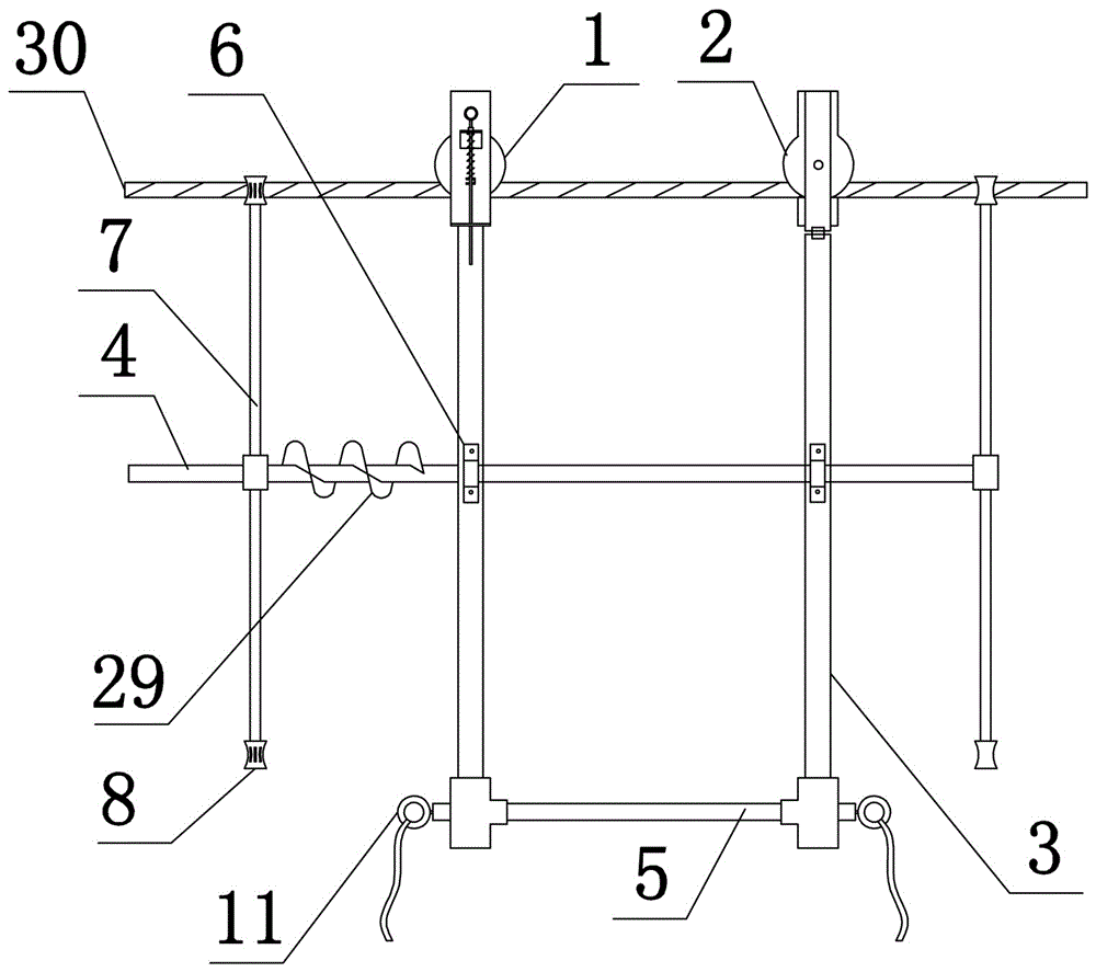
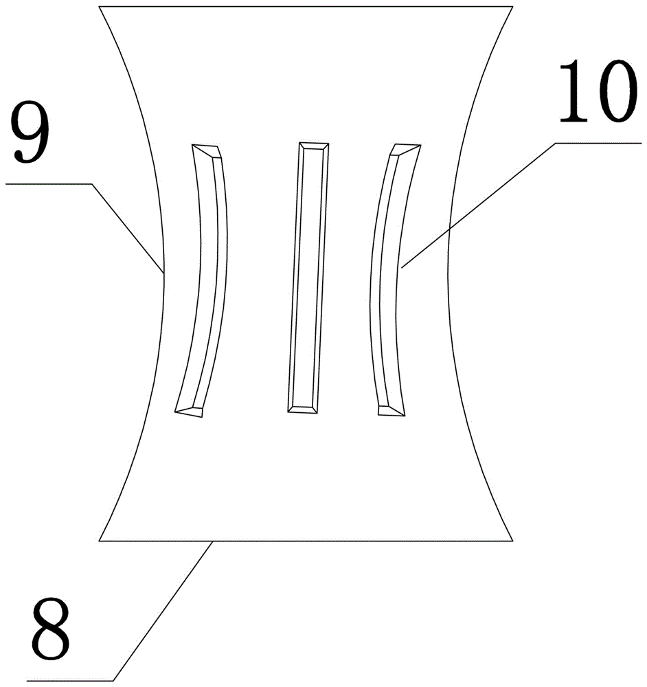
[0032] like figure 1 and figure 2 As shown, the present invention includes a support frame, a pulley one 1 and a pulley two 2, the support frame includes two vertical bars 3, an upper cross bar 4 and a lower cross bar 5, two hoops 6 are arranged on the upper cross bar 4, Two hoops 6 and the lower cross bar 5 are all fixedly connected with the two vertical bars 3, and the upper cross bar 4 is provided with a driving mechanism and a knocking mechanism. The driving mechanism is a screw rod 29, and the screw rod 29 is fixed on the surface of the upper cross bar 4 and With the coaxial rotation of the upper cross bar 4, the screw rod 29 is wound with a stay wire (not shown in the figure). The knocking mechanism includes a connecting rod 7 and an ice hammer 8 arranged at the end of the connecting rod 7. The ice hammer 8 is a columnar body, and the ice hammer 8 A groove 9 is provided on the surface, and the groove 9 is matched with the outer surface of the power transmission wire. The...

Embodiment 2

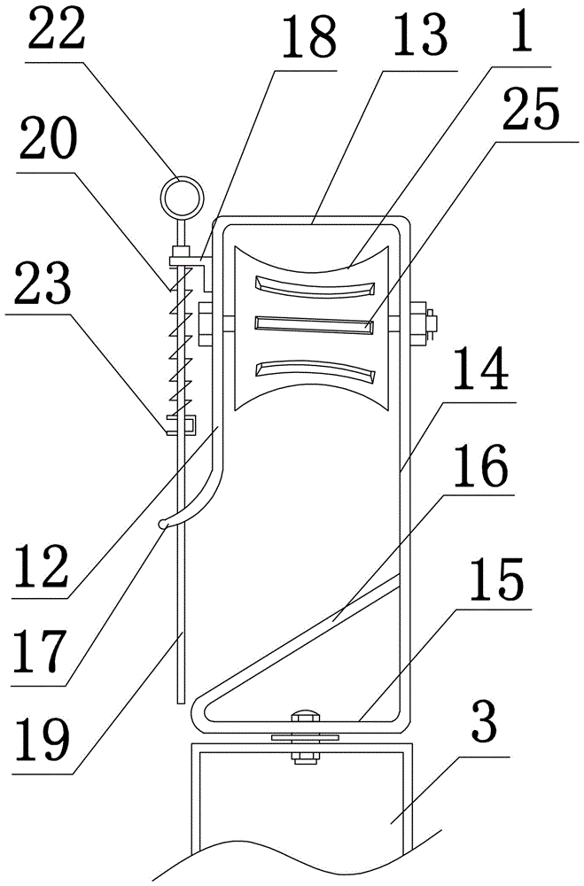
[0036] The structure of this embodiment is basically the same as that of Embodiment 1, the difference is: as Figure 5 As shown, a magnet one 27 is set between the inclined plate 16 and the horizontal plate two 15, and the lower end of the pull rod 19 is fixedly connected to the magnet two 28 which is attracted to each other by the magnet one 27. For the arc groove structure that cooperates with magnet one 27, the suction force F1 when magnet one 27 contacts with magnet two 28 is greater than the maximum elastic force F2 of spring 20, and the suction force F1 when magnet one 27 contacts with magnet two 28 is smaller than this Invent the self-weight G of the whole.

[0037] In this embodiment, the mutual attraction between the magnet one 27 set between the inclined plate 16 and the horizontal plate two 15 and the magnet two 28 set at the lower end of the pull rod 19 can effectively ensure the effect of automatic sealing, especially when the spring 20 is irreversibly shortened. ...

Embodiment 3

[0039] The structure of this embodiment is basically the same as that of Embodiment 1, the difference is: as Figure 6 to Figure 8 As shown, blunt protrusion one 25, blunt protrusion two 26 and blunt protrusion three 10 are all cross-shaped. Image 6 Only show the structure of the blunt protrusion three 10, the drive mechanism is a grooved roller 31, the groove bottom of the grooved roller 31 is provided with a tooth one 32, and a transmission belt 33 is arranged in the grooved roller 31, and the transmission belt 33 is arranged to match with the tooth one 32 Tooth 2:34. In this embodiment, the grooved roller 31 replaces the screw rod 29 in Embodiment 1, and the transmission belt 33 replaces the pull wire of Embodiment 1. The gear cooperation between the grooved roller 31 and the conveyor belt 33 effectively prevents the gap between the transmission belt 33 and the knocking mechanism. Slippage occurs.


PUM


Abstract

The invention discloses a deicing tackle for a power transmission line. The deicing tackle comprises a support rack and travelling pulleys. The support rack comprises two vertical rods, an upper transverse rod and a lower transverse rod. The end of the upper transverse rod is provided with a drive mechanical and a knocking mechanism. The knocking mechanism comprises a connecting rod and columnar ice hammers, and grooves are formed in the surfaces of the ice hammers. A hook is arranged at the upper end of each vertical rod. Each hook comprises a first vertical plate, a first horizontal plate, a second vertical plate, a second horizontal plate and an oblique plate, an arc-shaped plate is arranged at the lower end of the first vertical plate, a self-sealing mechanism is arranged above the arc-shaped plate and comprises a pull rod, a spring and a pull rod limit block, a pull ring is arranged at the top end of the pull rod, a limit pin is arranged on the pull rod, and the spring sleeves the pull rod. The deicing tackle has the advantages that ice coating the surfaces of wires can be eliminated comprehensively by the ice hammers with the grooves, the pull rods and the springs can be replaced fast after the limit pins are removed, and the problems of part aging and poor sealing effect after long-term use are solved.

Description

technical field [0001] The technical field of the power transmission line inspection and maintenance device of the present invention, in particular, relates to a power transmission line deicing block. Background technique [0002] In power transmission and transformation projects, the phenomenon of icing on wires is common, and the faults caused by icing on transmission lines have seriously affected the normal operation of the power system. The icing of wires is a complex process, and the amount of icing is related to factors such as wire radius, supercooled water droplet diameter, air volume, wind speed, wind direction, air temperature, and icing time. The icing of transmission lines can cause conductor galloping, tower tilting, tower collapse, transmission line disconnection, insulator flashover and other hazards, further causing major accidents. The commonly used method is the mechanical deicing method, which achieves the purpose of deicing by destroying the physical str...

Claims


Application Information

Patent Timeline
IPC IPC(8): H02G7/16
CPCH02G7/16
Inventor 王栋王运柯靳平徐杰钱金辉段晓张新凯王艺旋徐涛程元卿陈龙芮境泽
Owner 王忠强
Why Eureka
Try Eureka