Generator carbon brush on-line automatic constant voltage regulation and sweeping device
A technology of constant voltage regulation and constant voltage device, applied in the field of electric power, can solve problems such as hidden dangers of stable operation of equipment, increased contact pressure drop, and unstable contact, and achieve the effect of ensuring stable operation of equipment, consistent force, and convenient operation
- Summary
- Abstract
- Description
- Claims
- Application Information
AI Technical Summary
Problems solved by technology
Method used
Image
Examples
Embodiment 1
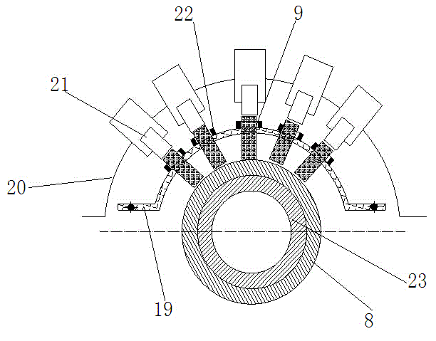
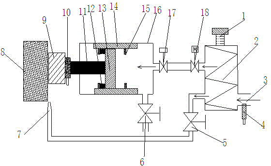
[0028] Example 1 : see figure 1 , figure 2 , as an improvement of the present invention, the automatic constant pressure adjustment and purging device includes a constant pressure device, a generator rotor 23, a carbon brush 9, a slip ring 8, a constant pressure device bracket 20, and a carbon brush bracket 19, the The slip ring 8 is rigidly connected to the generator rotor 23, the carbon brush 9 is in contact with the slip ring 8 under the fixation of the carbon brush bracket 19 and the brush holder 22, the constant voltage device 21 is fixed on the constant voltage device bracket 20, The constant pressure device includes a pneumatic propulsion device, a regulating device and a pressure regulator. The regulating device includes a pressure controller, a pressure regulating valve and a carbon brush pressure sensing element. To cool the purge assembly, the first path adjustment assembly includes a cut-off solenoid valve 17 and a pressure regulation valve 18, and the cut-off...
Embodiment 2
[0029] Example 2 : see figure 1 , figure 2 , as an improvement of the present invention, the pneumatic propulsion device 16 includes a pressure sensitive element 10, a push insulator 11, a compression spring 12, a sliding piston 13, a sliding notch 14, a stopper 15, and the sliding notch 14 The number is two groups, which are arranged on the upper and lower inner walls of the cylinder body of the pneumatic propulsion device. The sliding piston is embedded and installed between the upper and lower sliding notches, and the pushing insulator is arranged between the sensing element 10 and the sliding piston. The pressure sensing element It is fixedly installed on the push insulator, which is rigidly connected with the sliding piston.
Embodiment 3
[0030] Example 3 : see figure 1 , figure 2 , as an improvement of the present invention, the number of the stoppers 15 is two groups, which are installed on the upper and lower sliding notches correspondingly, each group has two stoppers, and the two stoppers are respectively arranged on the slide On the left and right sides of the piston, a compression spring 12 is arranged between the left stop block and the sliding piston 13 . The push insulator 11 is rigidly connected with the sliding piston, the pressure sensitive element is fixedly installed on the push insulator, the piston can move left and right, and the upper and lower sets of stoppers are fixedly installed on the movable notch to limit the displacement position of the piston.
PUM
 Abstract
Description
Claims
Application Information
 - R&D
- Intellectual Property
- Life Sciences
- Materials
- Tech Scout
- Unparalleled Data Quality
- Higher Quality Content
- 60% Fewer Hallucinations
Browse by: Latest US Patents, China's latest patents, Technical Efficacy Thesaurus, Application Domain, Technology Topic, Popular Technical Reports.
© 2025 PatSnap. All rights reserved.Legal|Privacy policy|Modern Slavery Act Transparency Statement|Sitemap|About US| Contact US: help@patsnap.com


