Circulating assembly device of automatic conveying equipment jig

A technology for assembling devices and transmission equipment, which is applied to other manufacturing equipment/tools, transportation and packaging, conveyors, etc., can solve problems such as unsmooth docking, vibration, and unstable structure of the production line, so as to save manufacturing time, reduce costs, The effect of improving fluency

Inactive Publication Date: 2016-12-07
SUZHOU KAILEISHENG AUTOMATION TECH CO LTD
View PDF6 Cites 14 Cited by
  • Summary
  • Abstract
  • Description
  • Claims
  • Application Information

AI Technical Summary

Problems solved by technology

[0004] The conveying production line is the most used assembly line for semi-manual work, but the track support and transmission power structure of the existing production line are generally separated, and the production line with this structure is prone to differences between the transmission part and the track in the working state. The degree of vibration caused the instability of the entire production line structure; or the transfer end of the jig that carries the product on the production line adopts a split structure, and the connection of the slide rail is not fixed with the transfer platform. The slide rail and the fixed end slide rail are not fixed on the same reference plane. In the production line with this structure, the relative position of the slide rail is in an active state when there is a docking process when the product transitions from the transfer platform slide rail to the fixed end slide rail. , the docking is not smooth

Method used


Image

  • Circulating assembly device of automatic conveying equipment jig
  • Circulating assembly device of automatic conveying equipment jig
  • Circulating assembly device of automatic conveying equipment jig

Examples


Embodiment Construction

[0030] The technical solutions of the embodiments of the present invention will be clearly and completely described below in conjunction with the accompanying drawings of the present invention.

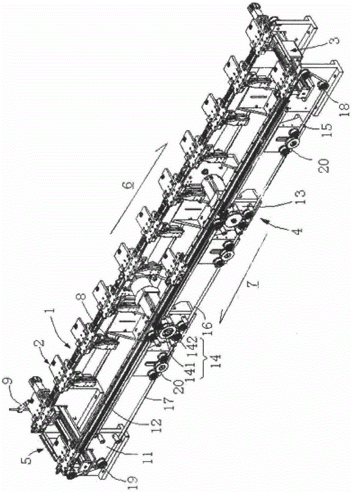
[0031] like figure 1 As shown, a circular assembly device for jigs of automated transmission equipment disclosed in an embodiment of the present invention includes a work position transmission line 1, a jig assembly 2, a tail slide rail module 3, a return side transmission line 4 and a head slide Rail module 5, working station conveying line 1 has a plurality of working stations for processing products, the products are carried by jig assembly 2, and jig assembly 2 carries the products to be assembled from the front end of working station conveying line 1 ,according to figure 1 In the direction 6 of the working position shown in , the products are sequentially transported to each working position of the working position conveying line 1 for assembly and processing, and the fixture as...


PUM


Abstract

The invention discloses a cycle assembly device for jigs of automatic transmission equipment, including jig components, and a working position transmission line connected to form a loop, a tail slide rail module, a return side transmission line, and a head slide rail module. There are multiple work stations for processing products on the work station transmission line. The products are carried by the jig assembly, and the jig assembly carries the product cycle from the head end of the work station conveying line to each work station for assembly and processing, and then sequentially passes through the The tail slide rail module, the return side conveyor line and the head slide rail module complete the product assembly. The overall structure of the present invention is stable, and the effective docking of the slide rails can prolong the life of the jig slider. The precise positioning of the jig can ensure the stability of the product assembly process, and the application of the timing belt improves the efficiency of the jig backflow application.

Description

technical field [0001] The invention relates to the field of automatic transmission equipment, in particular to a cycle assembly device for jigs of automatic transmission equipment. Background technique [0002] With the development of industrial automation, in order to improve product quality with high repeatability and consistency, improve product accuracy, reduce manufacturing costs, shorten manufacturing cycles and reduce the number of products in progress, and replace labor in harmful and dangerous environments. Operations, in some cases, can only be produced by automatic equipment, which reduces labor costs and is easy to manage. [0003] It is precisely because of the characteristics of high quality, high efficiency, low cost, and rapid manufacturing that automated production brings, manufacturing automated equipment will become the mainstream production mode in the future. Especially in the current global economic integration environment, to participate in internatio...

Claims


Application Information

Patent Timeline
Patent Type & Authority Applications(China)
IPC IPC(8): B23P23/00B65G35/00
CPCB23P23/00B65G35/00
Inventor 赵炳燚
Owner SUZHOU KAILEISHENG AUTOMATION TECH CO LTD
Why Eureka
Try Eureka