Railway vehicle traction system and railway vehicle

A rail vehicle and traction system technology, applied in the field of rail vehicle traction systems and rail vehicles, can solve the problems of high maintenance cost, regular maintenance, and large power loss, etc., to reduce installation space and vehicle weight, reduce weight costs, and improve efficiency Effect

Active Publication Date: 2016-12-07
CRRC TANGSHAN CO LTD
View PDF3 Cites 11 Cited by
  • Summary
  • Abstract
  • Description
  • Claims
  • Application Information

AI Technical Summary

Problems solved by technology

[0004] However, since the generator in the existing traction system uses an AC synchronous generator, the magnetic field of the AC synchronous generator is generated by an external excitation current, so an additional excitation control device is required, resulting in a complex structure of the entire traction system and a large volume. Larger, leading to an increase in the installation space of the traction system, which increases the weight, energy consumption and cost of the rail vehicle
Moreover, the motor is a DC motor, and the brushes of the DC motor need to be maintained regularly, the maintenance cost is high, and the power loss caused by the mechanical friction of the brushes is large, resulting in a decrease in the efficiency of the entire traction system

Method used


Image

  • Railway vehicle traction system and railway vehicle
  • Railway vehicle traction system and railway vehicle

Examples


Embodiment 1

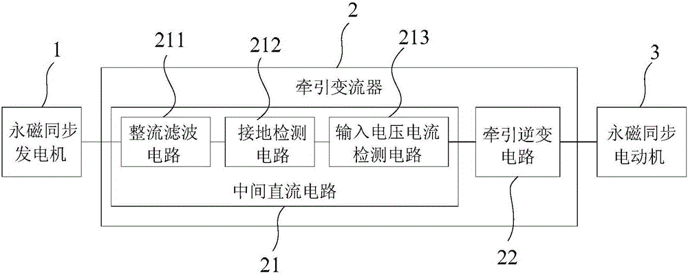
[0017] figure 1 For the structural block diagram of the rail vehicle traction system provided by Embodiment 1 of the present invention, refer to the attached figure 1 As shown, this embodiment provides a rail vehicle traction system. It should first be explained that the rail vehicles mentioned in this embodiment include but are not limited to diesel locomotives, railway vehicles, and EMUs.

[0018] The rail vehicle traction system of this embodiment includes: a permanent magnet synchronous generator 1 , a traction converter 2 and a permanent magnet synchronous motor 3 electrically connected in sequence. The permanent magnet synchronous generator 1 is mechanically connected with an external diesel engine (not shown in the figure), and is used to rotate under the drive of the diesel engine to provide three-phase AC power to the traction converter 2 .

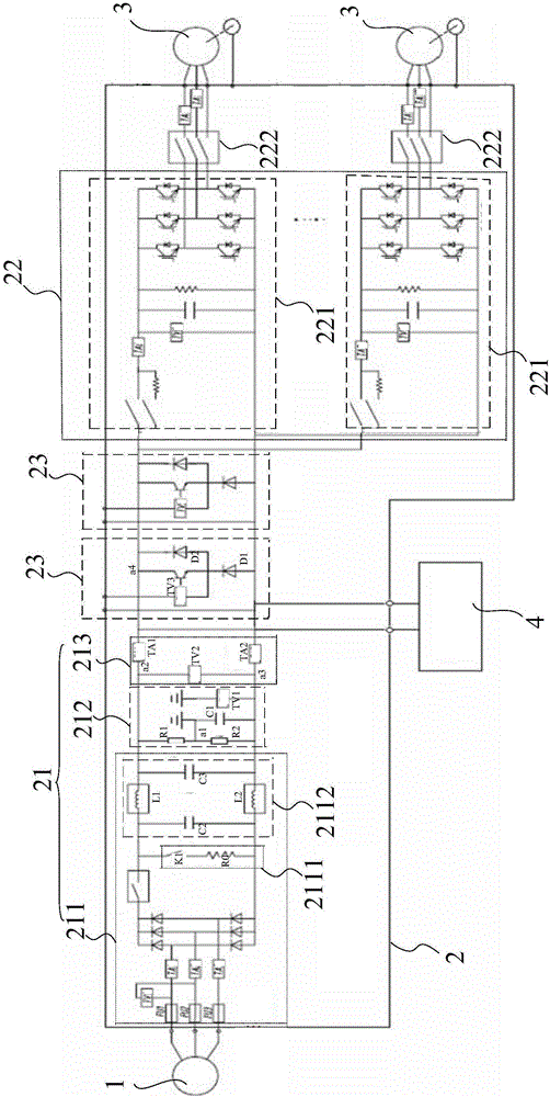
[0019] The traction converter 2 includes: an intermediate DC circuit 21 and a traction inverter circuit 22 . Wherein, the int...

Embodiment 2

[0032] This embodiment provides a rail vehicle, including: a vehicle body, a driver's cab, and a rail vehicle traction system. Wherein, the driver's cab is located at the end of the vehicle body, and the rail vehicle traction system is installed in the vehicle body for pulling the rail vehicle.

[0033] The rail vehicle traction system in this embodiment has the same structure as the rail vehicle traction system provided in Embodiment 1, and can achieve the same technical effect, so details will not be repeated here.


PUM


Abstract

The invention provides a railway vehicle traction system and a railway vehicle. The railway vehicle traction system comprises a permanent magnet synchronous generator, a traction converter and a permanent magnet synchronous motor. The permanent magnet synchronous generator is mechanically connected with an outer diesel engine and used for rotating under drive of the diesel engine so as to supply three-phase alternating current to the traction converter. The traction converter comprises a middle direct current circuit and a traction inversion circuit, the middle direct current circuit comprises a rectification and filter circuit, a grounding detection circuit and an input voltage and current detection circuit, all of which are sequentially and electrically connected, and the middle direct current circuit is used for supplying direct current voltage and protection to the traction inversion circuit; and the traction inversion circuit is electrically connected with the input voltage and current detection circuit and the permanent magnet synchronous motor and used for driving the permanent magnet synchronous motor, so that the permanent magnet synchronous motor drags the railway vehicle. Therefore, the efficiency of the whole traction system is improved, the installation space and the vehicle weight are reduced, and miniaturization, lightweight and low cost of the whole vehicle are achieved.

Description

technical field [0001] The invention relates to the technical field of rail vehicles, in particular to a rail vehicle traction system and a rail vehicle. Background technique [0002] The rail vehicle traction system is the power transmission system of the rail vehicle and is the core of the entire vehicle. [0003] The prior art rail vehicle traction system mainly includes: an AC synchronous generator, a traction converter and a DC motor which are electrically connected in sequence. The AC synchronous generator is connected with the external diesel engine, and the diesel engine drives the AC synchronous generator to generate three-phase alternating current, which supplies power for the traction converter, and drives the DC motor to rotate according to a certain law through the traction converter, so as to realize the traction of the rail vehicle. [0004] However, since the generator in the existing traction system uses an AC synchronous generator, the magnetic field of th...

Claims


Application Information

Patent Timeline
Patent Type & Authority Applications(China)
IPC IPC(8): B60L11/08H02K7/18B60L50/13
CPCB60L50/13H02K7/1807Y02T10/64Y02T10/72
Inventor 姜东杰康莉莉王鑫刘有峰孙树鑫
Owner CRRC TANGSHAN CO LTD
Why Eureka
Try Eureka