Steam generation device and method

A steam generating device and steam technology, which are used in steam generation, steam boilers, firebox-type steam boilers, etc., can solve the problems of poor safety and high operating costs, and achieve the effects of reducing the probability of explosion, reducing operating costs and high efficiency.

Active Publication Date: 2016-12-07
浙江炬德能源科技有限公司
View PDF6 Cites 0 Cited by
  • Summary
  • Abstract
  • Description
  • Claims
  • Application Information

AI Technical Summary

Problems solved by technology

[0007] In order to overcome the problems of high operating cost and poor safety of existing steam generators, the present invention provides a steam generating device

Method used


Image

  • Steam generation device and method
  • Steam generation device and method

Examples


Embodiment 1

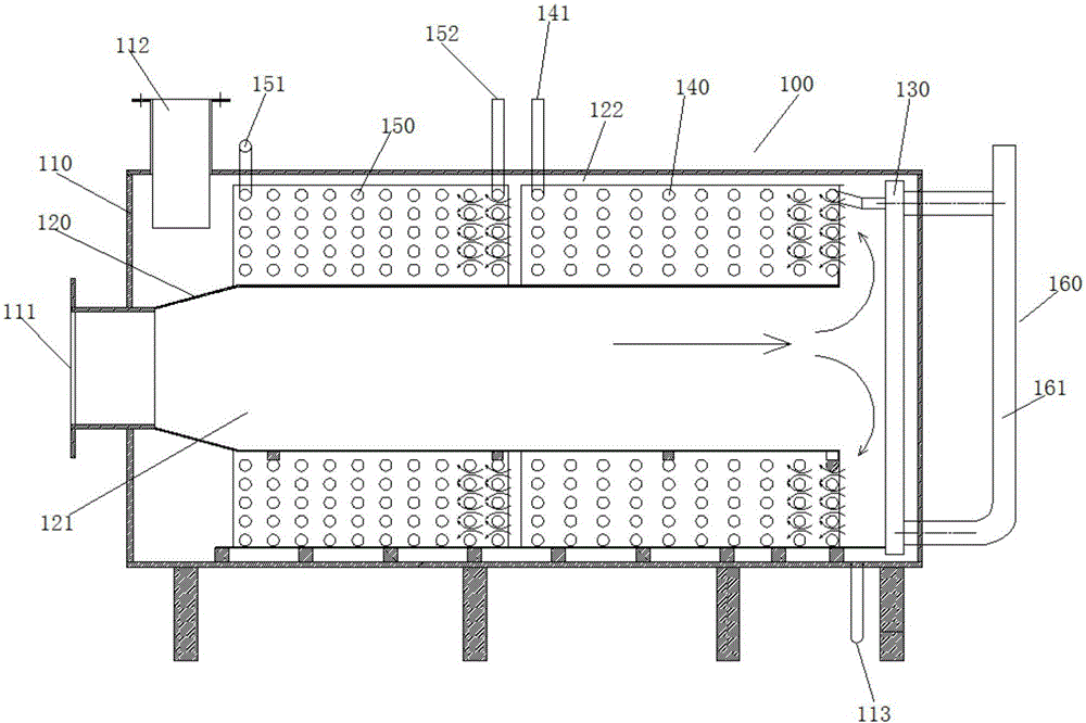
[0031] Such as figure 1 As shown, this embodiment provides a heating unit for a steam generator, which includes a closed casing 110, and a heating channel with both ends communicating with the outside is provided in the casing 110; A combustion channel 121 that injects flames inward in the horizontal direction, and a smoke flow channel 122 for exhausting combustion smoke. The discharge direction of the combustion smoke at the smoke flow channel 122 is opposite to the injection direction of the flame at the combustion channel 121; A first heating unit 130 is provided at the turning connection between the combustion channel 121 and the flue gas flow channel 122, a second heating unit 140 is provided at the flue gas flow channel 122, and both the first heating unit 130 and the second heating unit 140 are equipped with flow channels and communicate with each other.

[0032] In this embodiment, the first heating unit 130 and the second heating unit 140 are mainly heated by combust...

Embodiment 2

[0047] This embodiment provides a steam generator, including a generator body 100 . Its generator body 100 includes the heating unit in Embodiment 1.

[0048] In this embodiment, the bottom of the casing 110 is further provided with a sewage outlet 113 , and the sewage outlet 113 is located below the turn-back connection between the combustion channel 121 and the flue gas flow channel 122 .

[0049] In this embodiment, the setting of the sewage outlet 113 can conveniently clean up the combustion residue at the combustion channel 121; in addition, the sewage outlet 113 is located below the turning joint between the combustion channel 121 and the flue gas flow channel 122, because the combustion channel Driven by the internal airflow, the combustion residue at 121 will accumulate under the turn-back connection, so that the combustion residue can be better discharged.

[0050] In this embodiment, a sewage valve is provided at the sewage outlet 113 .

[0051] In this embodiment,...

Embodiment 3

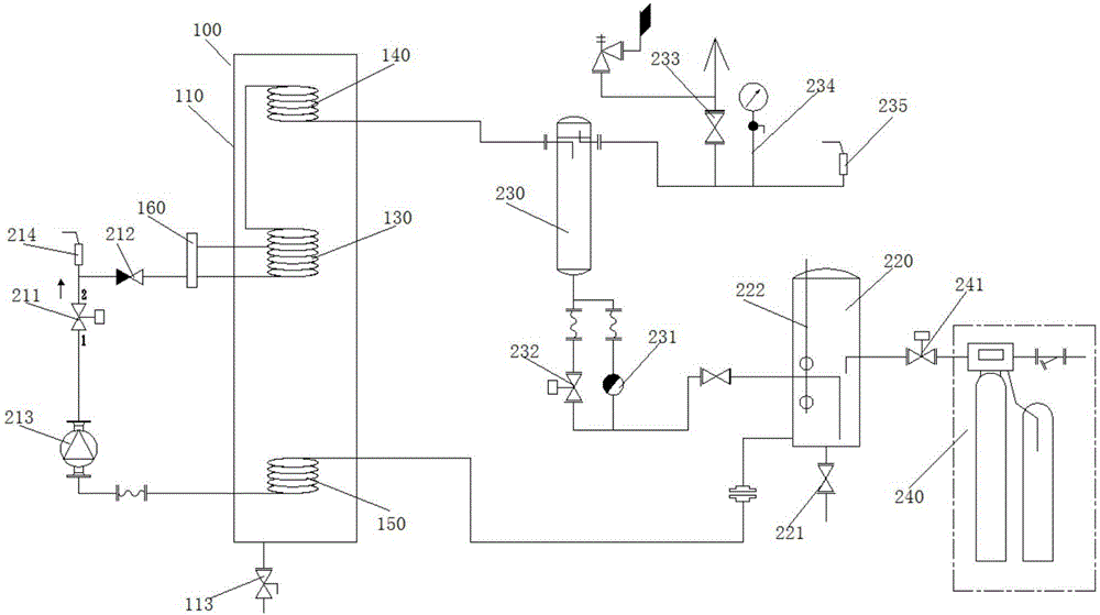
[0055] Such as figure 2 As shown, this embodiment provides a steam generating unit, and its specific structure can adopt the corresponding form in Embodiment 1 or 2. It includes a heating channel set in a closed casing 110, both ends of which communicate with the outside world, and the heating channel is provided with a first heating unit 130, a second heating unit 140 and a preheating unit 150 in the direction from the inlet to the outlet; The first heating unit 130, the second heating unit 140 and the preheating unit 150 are all provided with water flow passages, and the internal water flow passages of the preheating unit 150, the first heating unit 130 and the second heating unit 140 are connected in sequence, and the preheating unit 150 A pressure regulating valve 211 and a check valve 212 are also sequentially connected to the first heating unit 130 by pipelines.

[0056] In this embodiment, the check valve 212 can preferably isolate the preheating unit 150 from the fir...


PUM


Abstract

The invention relates to the technical field of steam generation devices, in particular to a steam generation device and method. The device comprises a generation device body which comprises a shell, and a burner connector part and a smoke discharge opening are formed in the same end of the shell; the shell is internally and horizontally provided with a combustion barrel with two open ends; one end of the combustion barrel is communicated with the burner connector part, and the other end of the combustion barrel is far away from the opposite inner wall of the shell; a first heating coiler is arranged in the shell in a manner of being opposite to the other end of the combustion barrel, and a second heating coiler and a preheating coiler are sequentially arranged at the position of the outer wall between the other end of the combustion barrel and the smoke discharge opening; one end of the preheating coiler is connected with a water supply system, and the other end of the preheating coiler is connected with one end of the first heating coiler through a pressure adjusting valve and a check valve in sequence; and the other end of the first heating coiler is connected with one end of the second heating coiler, and the other end of the second heating coiler is connected with a steam treatment system. The steam generation device and method are higher in heat using rate and safer and more reasonable.

Description

technical field [0001] The invention relates to the technical field of steam generators, in particular to a steam generating device and method. Background technique [0002] The steam generator is an important part of the steam power plant, and it is a mechanical device that uses the heat energy of fuel or other energy sources to heat water into hot water or steam. [0003] Existing steam generators are usually in the form of boilers. When this type of boiler is heated, in order to reduce the thermal stress concentration at the weld between the thin-walled tube and the thick-walled drum and the tube sheet, the boiler must be slowly Heating, this just makes existing boiler need to spend a large amount of time (being at least 40 minutes) from cold pan start to steam output, and this has brought great inconvenience for the user. [0004] The patent document with the publication number "CN201513874U" discloses a fast steam generator. Although it can greatly increase the speed o...

Claims


Application Information

Patent Timeline
IPC IPC(8): F22B13/04F22B31/08
Inventor 白传贞
Owner 浙江炬德能源科技有限公司
Why Eureka
Try Eureka