Shell and Tube Condenser and Air Conditioning System

A condenser and shell-and-tube technology, which is used in the field of shell-and-tube condensers and air conditioning systems, can solve the problems of liquid in the suction of the compressor, rising unit cost, and malfunction of the expansion valve, so as to increase the degree of turbulence, improve the replacement Thermal efficiency, thickness reduction effect

Active Publication Date: 2018-12-21
上海冰核时代科技中心(有限合伙)
View PDF7 Cites 0 Cited by
  • Summary
  • Abstract
  • Description
  • Claims
  • Application Information

AI Technical Summary

Problems solved by technology

If the degree of superheat or subcooling is not enough, it will bring many problems to the refrigeration system, such as compressor suction with liquid, cooling capacity reduction, expansion valve malfunction, etc.
[0003] A gas-liquid separator is usually installed after the evaporator in a large air-conditioning unit to prevent the compressor from sucking liquid, and a subcooler is installed after the condenser to increase the cooling capacity, but this will increase the cost of the unit and increase the cost of the unit. The pipeline is very complicated

Method used


Image

  • Shell and Tube Condenser and Air Conditioning System
  • Shell and Tube Condenser and Air Conditioning System
  • Shell and Tube Condenser and Air Conditioning System

Examples


Embodiment Construction

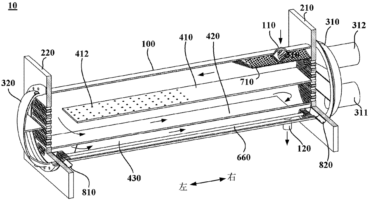
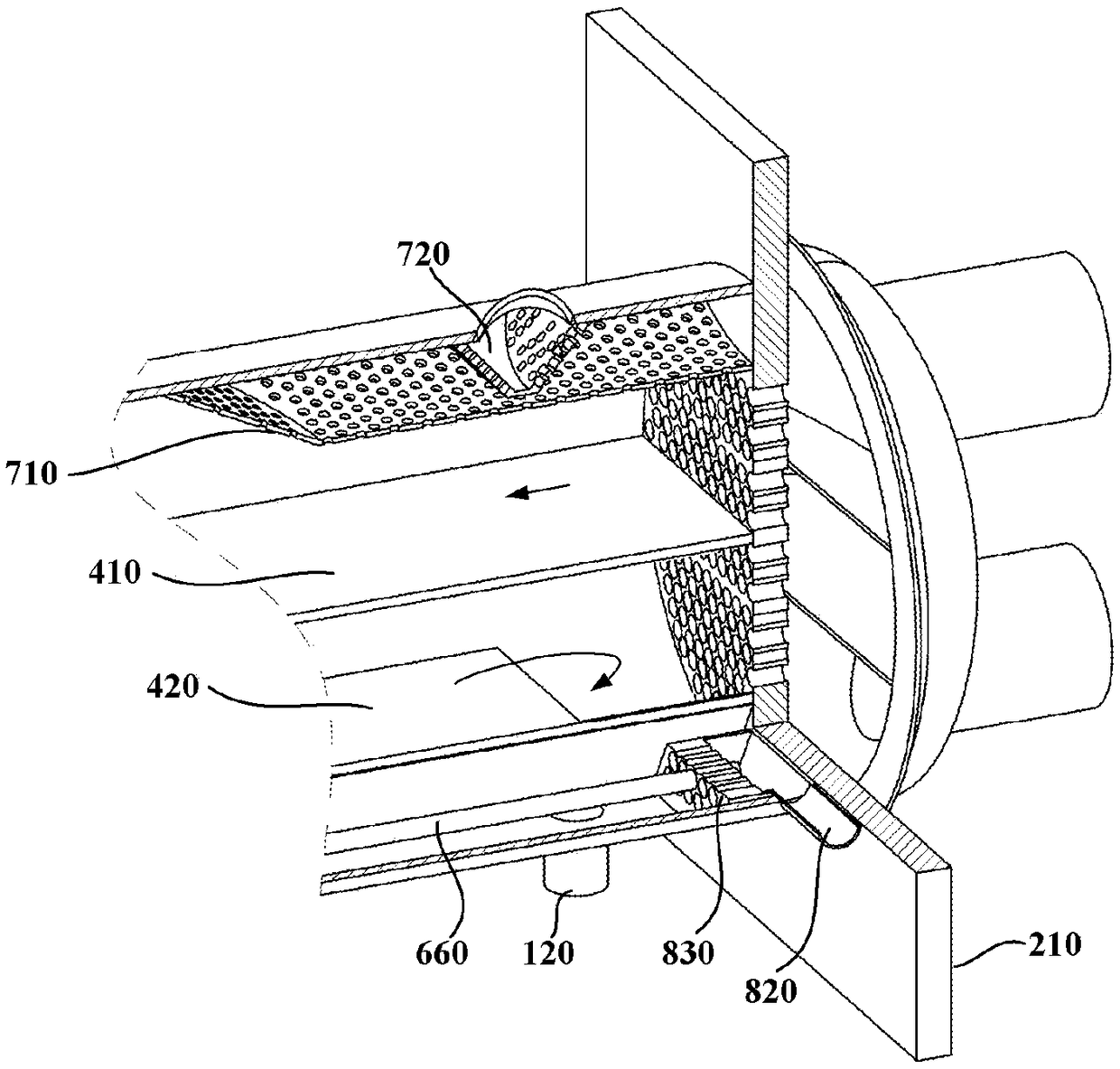
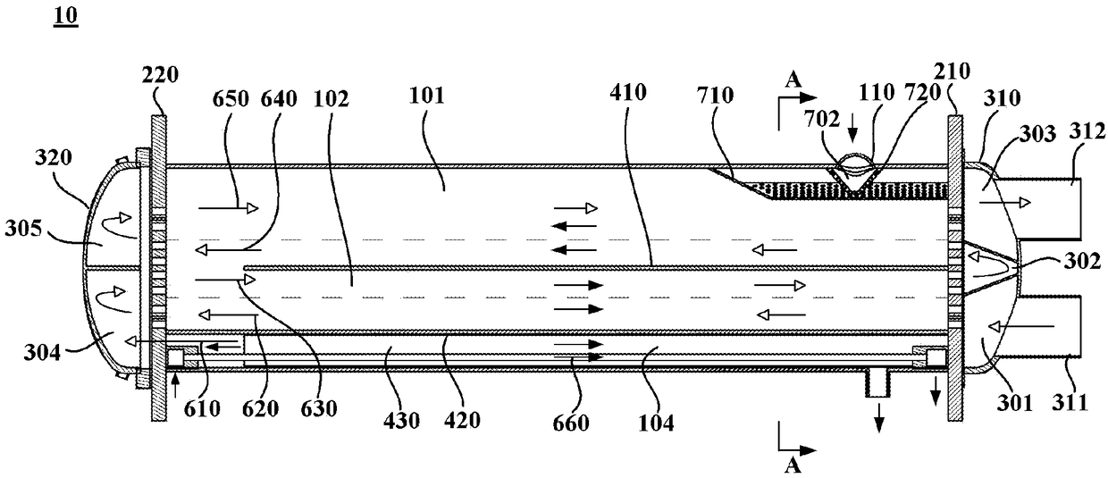
[0031] figure 1 It is a schematic three-dimensional sectional view of a shell-and-tube condenser according to an embodiment of the present invention; figure 2 yes figure 1 A partial enlarged view of the right structure of the shell-and-tube condenser; image 3 It is a plane sectional view of a shell-and-tube condenser according to an embodiment of the present invention; Figure 4 yes image 3 A-A sectional view of the shell-and-tube condenser shown. Such as figure 1 with figure 2 As shown, the embodiment of the present invention provides a shell and tube condenser, which is used in a vapor compression refrigeration cycle system. The shell-and-tube condenser 10 may generally include a shell 100 , a first tube sheet 210 and a second tube sheet 220 , a first tube box 310 and a second tube box 320 , and a heat exchange tube bundle. Wherein, the casing 100 is provided with a condensate inlet 110 for communicating with the exhaust port of the compressor, and a condensate ou...


PUM


Abstract

The invention provides a shell and tube type condenser and an air conditioning system. The shell and tube type condenser comprises a shell, a first tube plate, a second tube plate, a first channel, a second channel, a heat exchange tube bundle and a heat regenerative tube bundle, wherein the shell is provided with a condensate gas inlet used for communicating with a compressor exhaust port, a condensate liquid outlet used for communicating with a throttling element liquid inlet, a heat regenerative gas inlet used for communicating with an evaporator gas outlet, and a heat regenerative gas outlet used for communicating with a compressor gas suction port; the first tube plate and the second tube plate are arranged at the axial two ends of the shell correspondingly; the first channel and the second channel are arranged outside the first tube plate and the second tube plate correspondingly, and a cooling water inlet and a cooling water outlet are formed in the first channel or the second channel; the heat exchange tube bundle is arranged inside the shell, and the two ends of the heat exchange tube bundle communicate with the first channel and the second channel correspondingly and fixed to the first tube plate and the second tube plate correspondingly; and the heat regenerative tube bundle is arranged inside the shell, and the two ends of the heat regenerative tube bundle communicate with the heat regenerative gas inlet and the heat regenerative gas outlet correspondingly. According to the shell and tube type condenser and the air conditioning system, a freezing medium in the shell is utilized for conduction heat regeneration on exhaust gas of an evaporator, and meanwhile, supercooling of a freezing medium in the condenser is achieved.

Description

technical field [0001] The invention relates to the technical field of air conditioning, in particular to a shell and tube condenser and an air conditioning system. Background technique [0002] In the vapor compression refrigeration cycle system, usually the suction temperature of the compressor should be higher than the evaporation temperature of the evaporator, even if the suction has a certain degree of superheat, so that the temperature of the refrigerant before throttling (subcooling temperature) is lower than that of the condenser Condensation temperature, that is, the refrigerant has a certain degree of subcooling before throttling. If the degree of superheat or subcooling is not enough, it will bring many problems to the refrigeration system, such as compressor suction liquid, cooling capacity reduction, expansion valve malfunction and so on. [0003] A gas-liquid separator is usually installed after the evaporator in a large air-conditioning unit to prevent the co...

Claims


Application Information

Patent Timeline
Patent Type & Authority Patents(China)
IPC IPC(8): F25B39/04
CPCF25B39/04F25B2339/04Y02P80/15
Inventor 不公告发明人
Owner 上海冰核时代科技中心(有限合伙)
Why Eureka
Try Eureka