
Large view field super resolution imaging device

A technology of super-resolution imaging and large field of view, applied in the field of imaging technology research, can solve the problems such as the need to improve the resolution of the lens, the inability to break through the diffraction limit, and the large size of the lens. rate effect

Active Publication Date: 2016-12-07
INST OF OPTICS & ELECTRONICS - CHINESE ACAD OF SCI
View PDF5 Cites 9 Cited by
  • Summary
  • Abstract
  • Description
  • Claims
  • Application Information

AI Technical Summary

Problems solved by technology

However, due to the limitation of spherical symmetry, its thickness is almost equal to the structure diameter, resulting in large and bulky lenses
In addition, due to the inability to break through the diffraction limit, the resolution of traditional lenses needs to be improved

Method used


Image

  • Large view field super resolution imaging device
  • Large view field super resolution imaging device
  • Large view field super resolution imaging device

Examples


Embodiment Construction

[0022] The present invention will be described in detail below in conjunction with the accompanying drawings and specific embodiments, but the scope of protection of the present invention is not limited to the following examples, but should include all content in the claims. Moreover, those skilled in the art can realize all the content in the claims from the following embodiment.

[0023] The specific method of designing and manufacturing a large field of view super-resolution imaging device of the present invention is as follows:

[0024] (1) Design.

[0025] Firstly, the phase is predefined on the metasurface as shown in equation (1):

[0026] Φ ( r ) = k 0 r 2 2 f , - - - ( 1 )

[00...


PUM


Abstract

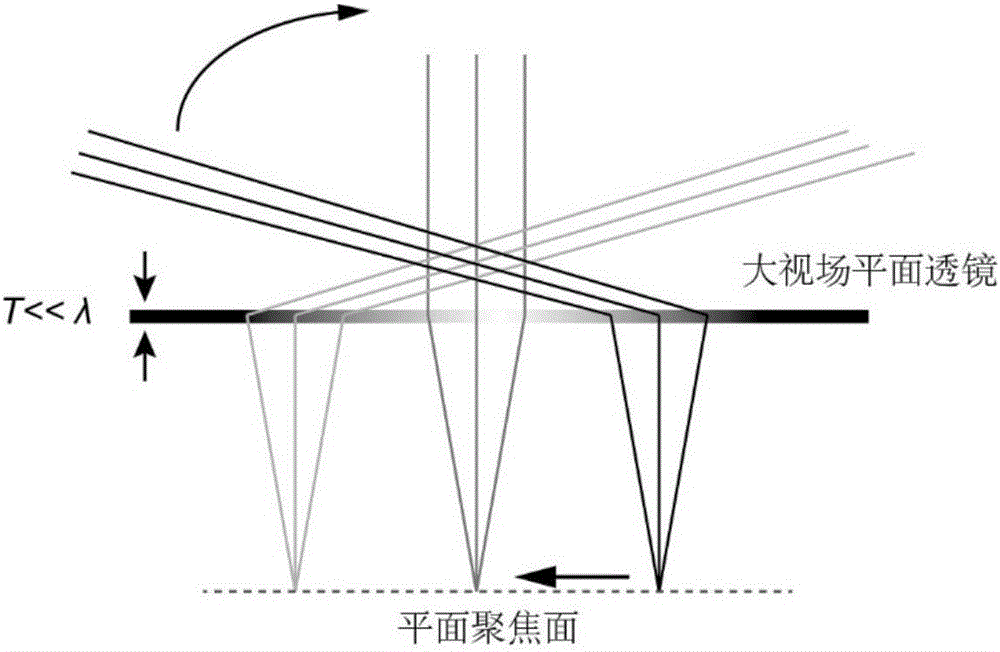
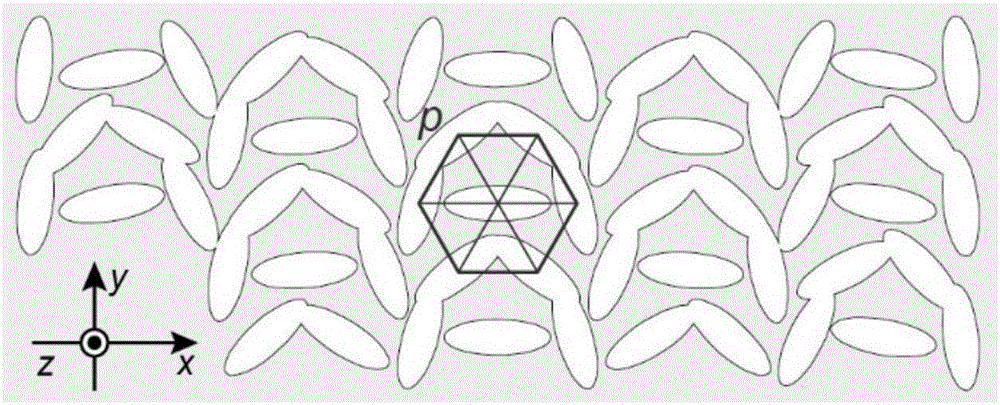
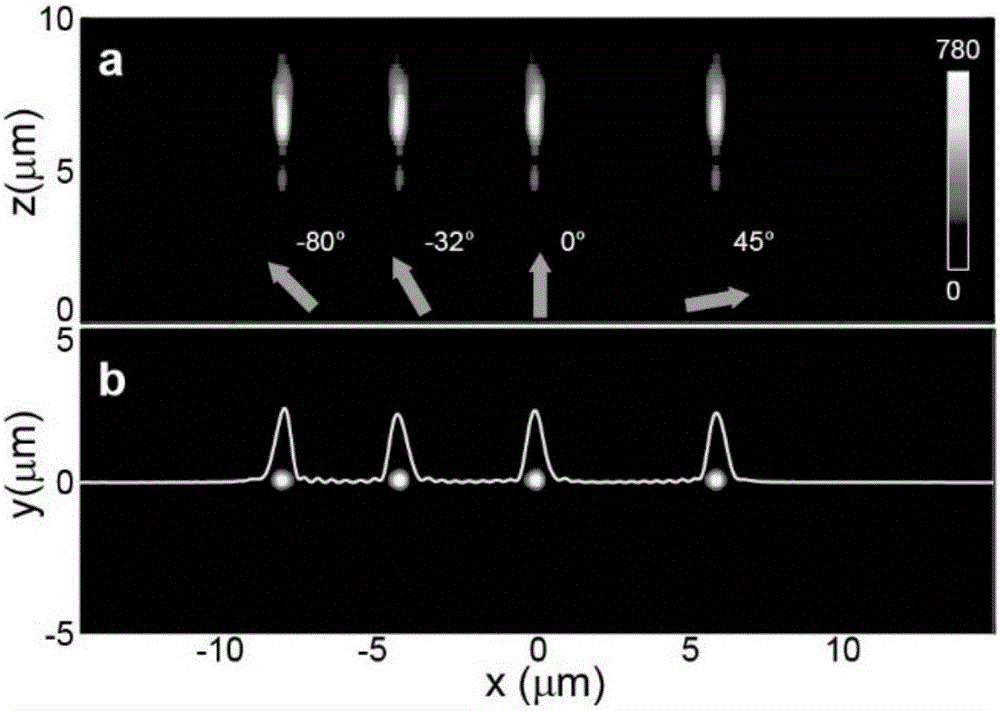
The invention discloses a large view field super resolution imaging device which comprises a base and a super-surface, wherein the base and the super-surface are successively arranged in the bottom-up sequence. The super-surface is composed of nano-unit structure arrays which are arranged in succession on an ultra-thin metal or a dielectric film. A nano-unit structure is a deep sub-wavelength structure. According to the invention, geometric phase on the nanostructure is used to control the electromagnetic wave symmetry; electromagnetic waves are converted from rotation symmetry to translational symmetry to acquire large view field perfect focusing near 180 degrees; if curved face or multi-plane combination is used, large view field imaging can be realized; the work bandwidth can cover the entire electromagnetic spectrum; the resolution is close to or even beyond the diffraction limit; and the device has a wide application prospect in the field of large view field super resolution imaging.

Description

technical field [0001] The invention relates to the field of imaging technology research, in particular to a large field of view super-resolution imaging device. Background technique [0002] Nature is the source of human learning, the source of human innovation, and the source of human wisdom. Many animals with compound eyes have a wide field of view, up to 360°. This feature is one of the most striking optical properties of the visual systems of these animals and has therefore attracted great academic interest. This inspires people to create some lenses with a large field of view by imitating the eyes of animals, such as: fisheye lenses, artificial fly eye lenses, etc. Due to the limitation in principle, it is very difficult to manufacture and implement these lenses in an integrated system. [0003] Theoretically, the concept of field of view can be explained by symmetry theory, which is very important for various optical problems, such as supersymmetry, anisotropy, chi...

Claims


Application Information

Patent Timeline
Patent Type & Authority Applications(China)
IPC IPC(8): G02B27/58
CPCG02B27/58
Inventor 罗先刚蒲明博赵泽宇王彦钦李雄马晓亮王长涛
Owner INST OF OPTICS & ELECTRONICS - CHINESE ACAD OF SCI
Learn More