
Prediction method of distributed thermal environment parameters for aircraft with complex shape based on database

A technology of thermal environment parameters and prediction methods, applied in prediction, data processing applications, electrical digital data processing, etc., can solve the problems of airflow mutual interference shock wave interference, low efficiency, high difficulty, etc., to reduce design time and improve prediction Efficiency, the effect of reducing the forecast period

Active Publication Date: 2019-08-09
BEIJING LINJIN SPACE AIRCRAFT SYST ENG INST +1
View PDF4 Cites 0 Cited by
  • Summary
  • Abstract
  • Description
  • Claims
  • Application Information

AI Technical Summary

Problems solved by technology

However, the shape of high-speed spacecraft is complex, the airflow mutual interference and shock wave interference characteristics are obvious, and it is difficult to accurately predict the thermal environment. The simulation parameters of the ground wind tunnel test cannot cover and completely simulate the high-speed flight environment, which is suitable for traditional spherical cones. The aerothermal engineering prediction method for simple shapes is not suitable for complex shapes, especially for the prediction of the thermal environment in local interference areas.
At the same time, large-scale parallel numerical calculations can be used to predict aircraft thermal environment parameters, but the prediction cycle is too long, difficult, and inefficient, and it is difficult to provide data for the design of anti-heat insulation systems in the design phase of aircraft with complex shapes

Method used


Image

  • Prediction method of distributed thermal environment parameters for aircraft with complex shape based on database
  • Prediction method of distributed thermal environment parameters for aircraft with complex shape based on database
  • Prediction method of distributed thermal environment parameters for aircraft with complex shape based on database

Examples


Embodiment

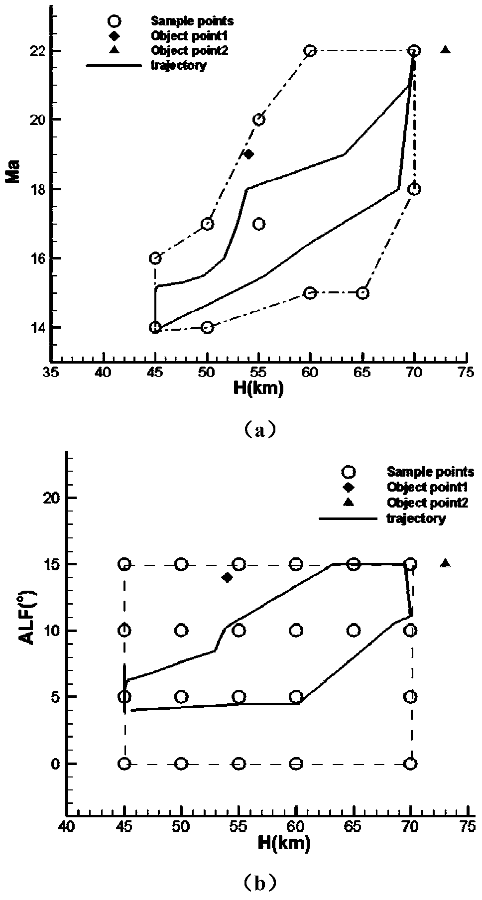
[0072] For the Hermes space shuttle test model, the distributed thermal environment parameter prediction is carried out. The model has no air rudder. Therefore, the selected working condition parameters are altitude, Mach number and angle of attack.

[0073] The database is constructed according to the flight altitude H, flight Mach number Ma, and range of attack angle ALF. It is assumed that the altitude H is between 45km and 70km, the Mach number Ma is between 14 and 22, and the attack angle ALF is between 0° and 15°. According to the measurement data of ground wind tunnel thermal test and flight test, the numerical calculation method using Roe format in spatial discrete format is suitable for the calculation of surface heat flow of the shape and working condition parameters.

[0074] figure 2 The altitude, Mach number and angle of attack distribution corresponding to the state points of the established aircraft surface heat flow parameter database are given, where (a) is t...


PUM


Abstract

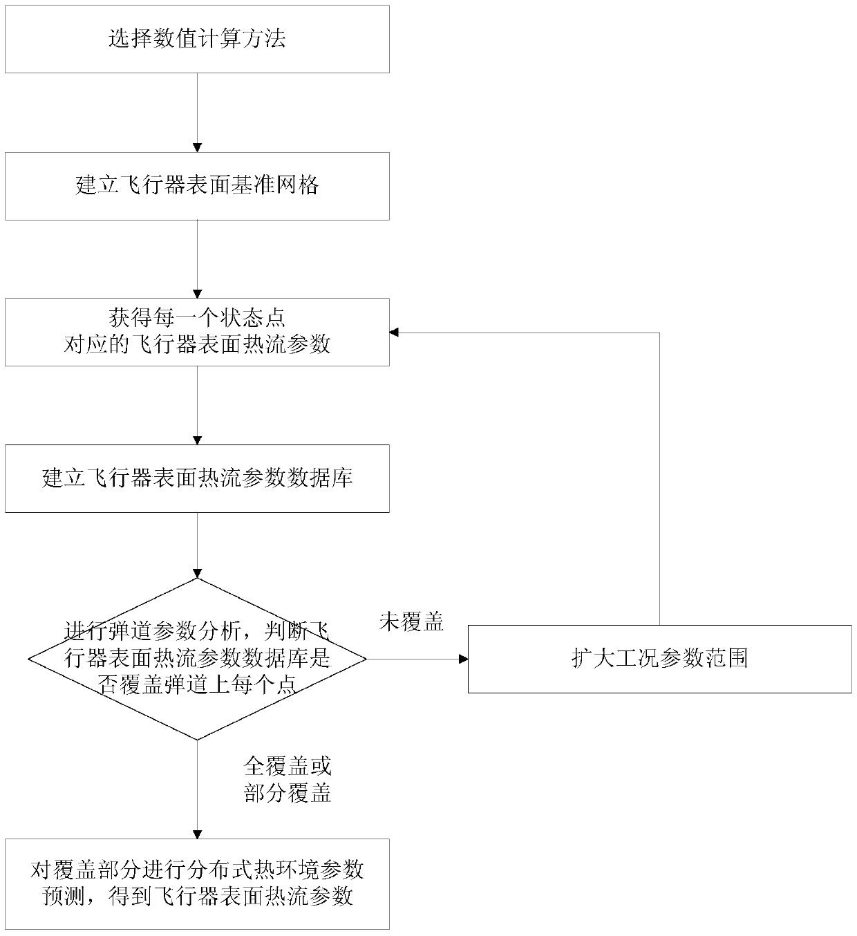
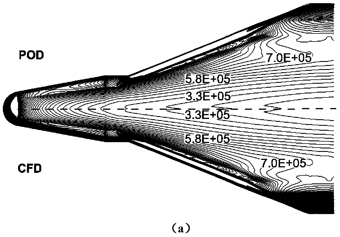
The invention discloses a database based complex-contour aircraft distributed heat environment parameter prediction method and belongs to the field of aircraft heat environment design. The method comprises the steps that an aircraft surface heat flow database is established, order reducing processing is conducted on the database by utilizing a POD method to obtain orthogonal basis vectors of the database, and aircraft surface heat environment parameters can be predicted along a ballistic trajectory by combining with a corresponding basic coefficient interpolation method. The method can really reflect the space distribution characteristics and interference characteristics of the aerodynamic heat environment for all points on the surface of a complex-contour aircraft. Value result comparison shows that the method can remarkably improve the computational efficiency, and prediction precision is not lost. A surface distributed heat flow is provided for calculation of a heat proof temperature field through the points along the ballistic trajectory, more exquisite temperature distribution can be obtained, and accordingly the design level of a whole heat preventing and insulation system is improved.

Description

[0001] Technical field: [0002] The invention relates to a method for quickly predicting distributed thermal environment parameters, which is mainly used for rapidly predicting the thermal environment parameters of various parts of an aircraft with complex shapes including wings, rudders and other components along a typical trajectory, and belongs to the field of spacecraft thermal environment design. [0003] Background technique: [0004] Prediction of aircraft distributed thermal environment parameters is the premise of anti-insulation system design. The traditional simple-shaped spacecraft distributed thermal environment parameter prediction can be obtained by ground wind tunnel thermal test or aerothermal engineering prediction method. However, the shape of high-speed spacecraft is complex, the airflow mutual interference and shock wave interference characteristics are obvious, and it is difficult to accurately predict the thermal environment. The simulation parameters of ...

Claims


Application Information

Patent Timeline
Patent Type & Authority Patents(China)
IPC IPC(8): G06F17/50G06Q10/04
CPCG06F30/15G06F30/367G06F2119/08G06Q10/04Y02T90/00
Inventor 聂春生黄建栋李宇檀妹静聂亮王迅王毓栋曹占伟陈敏潘红九闵昌万阎君
Owner BEIJING LINJIN SPACE AIRCRAFT SYST ENG INST
Learn More