

A flexible solar cell
A solar cell and flexible technology, applied in circuits, electrical components, photovoltaic power generation, etc., can solve the problems of poor photoelectric conversion efficiency and low qualification rate of flexible solar cells, so as to improve the yield rate, reduce the loss of photoelectric conversion efficiency, and save manufacturing Effects of Cost and Manufacturing Time
- Summary
- Abstract
- Description
- Claims
- Application Information
AI Technical Summary
Problems solved by technology
Method used
Image

Examples
preparation example Construction
[0045] The method for preparing the above-mentioned flexible solar cell is prepared sequentially in the order of a reflective metal layer, a multi-layer photoactive layer, a transparent conductive layer and a metal grid, when the flexible solar cell includes a hole blocking layer and / or an electron blocking layer , then add preparation steps between the corresponding steps;
[0046] Among them, the preparation method of photoactive layer, intermediate layer, electron blocking layer, hole blocking layer and transparent conductive layer can be prepared by coating method, while reflective metal layer and metal grid can be prepared by magnetron sputtering, vacuum thermal evaporation or nanometer Particle spray preparation.
Embodiment 1
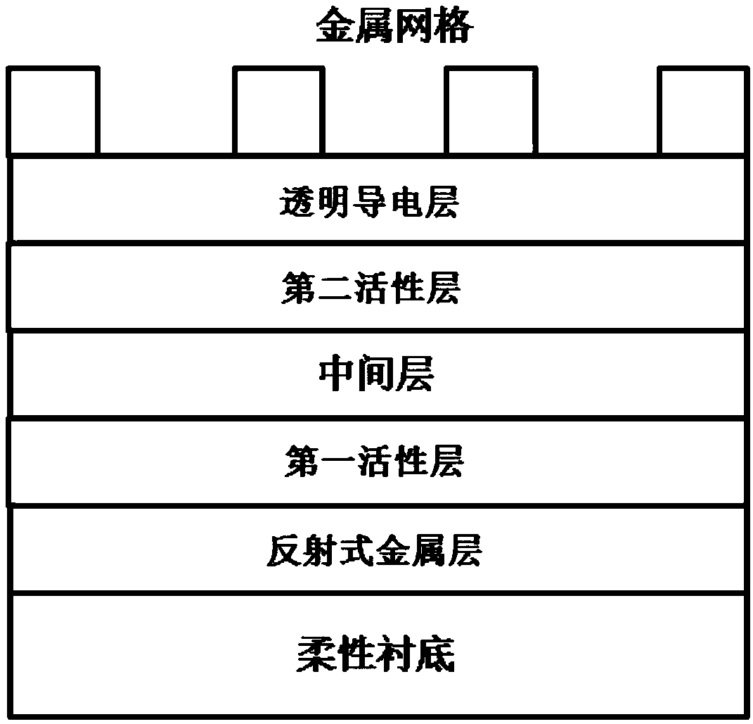
[0066] The area of the solar cell of embodiment 1 is 10cm 2 , including: polyethersulfone film as a flexible substrate, 80nm to 100nm silver as a reflective metal layer, 5nm PEI (polyetherimide) as a hole blocking layer, and 180nm first active layer (including P3HT and ICBA with a mass ratio of 1:1, the middle layer (composed of 1mm PEDOT:PSS and 5nm PEI in sequence from the bottom to the top surface), 80nm second active layer (PTB7-Th:PC 71 BM), 120nm PEDOT:PSS as transparent conductive layer and 80nm silver metal grid, such as figure 1 Shown; The preparation method of this solar cell comprises the following steps:
[0067]S1. Cut out a polyethersulfone film with a side length of 5 cm, cover it with tape, and vacuum evaporate to obtain a silver electrode with a side length of 4 cm in the central area, with a thickness of 80 nm to 100 nm. One side of the silver electrode is additionally vapor-deposited to the edge of the flexible substrate for easy contact testing. Spin-c...
PUM
 Abstract
Description
Claims
Application Information