Dual-band dual-polarization wave-beam-controllable microstrip reflective array antenna

A reflectarray antenna, dual-polarization technology, applied in the directions of antennas, waveguide horns, electrical components, etc., can solve the problems of fixed, discrete, and limited antenna application range of microstrip reflectarray antennas, so as to overcome continuous beam scanning and expansion. Application range, the effect of continuous beam scanning

Active Publication Date: 2016-12-07
XIDIAN UNIV
View PDF3 Cites 18 Cited by
  • Summary
  • Abstract
  • Description
  • Claims
  • Application Information

AI Technical Summary

Problems solved by technology

However, the deficiencies that still exist in this antenna structure are, first, because the antenna structure is fixed, the antenna can only work at a single operating frequency and a single polarization mode, which cannot meet the needs of radar and communication systems for multifunctional antenna systems
Second, although the antenna realizes beam scanning, the antenna can only realize discrete beam scanning and cannot realize beam continuous scanning
However, the deficiencies of this antenna structure still exist. First, due to the fixed structure of the antenna, the antenna can only work at a single operating frequency and a single polarization mode, which limits the application range of the antenna and cannot meet the needs of radar and communication systems. The Need for a Multi-Functional Antenna System
Second, although the antenna realizes beam scanning, it adopts a mechanical rotation structure, which can only realize discrete beam pointing, and cannot realize continuous beam scanning
[0005] To sum up, the current microstrip reflectarray antenna is facing two problems. One is that the existing microstrip reflectarray antenna can only work at a single operating frequency and a single polarization mode due to its fixed structure, which cannot meet the needs of radar and communication. System requirements for multifunctional antenna systems
The second is that the existing traditional beam-scanning microstrip reflectarray antenna loaded with MEMS switches and digital phase shifters can only realize discrete beam scanning and cannot realize beam continuous scanning

Method used


Image

  • Dual-band dual-polarization wave-beam-controllable microstrip reflective array antenna
  • Dual-band dual-polarization wave-beam-controllable microstrip reflective array antenna
  • Dual-band dual-polarization wave-beam-controllable microstrip reflective array antenna

Examples


Embodiment Construction

[0022] The present invention will be described in further detail below in conjunction with the accompanying drawings and embodiments.

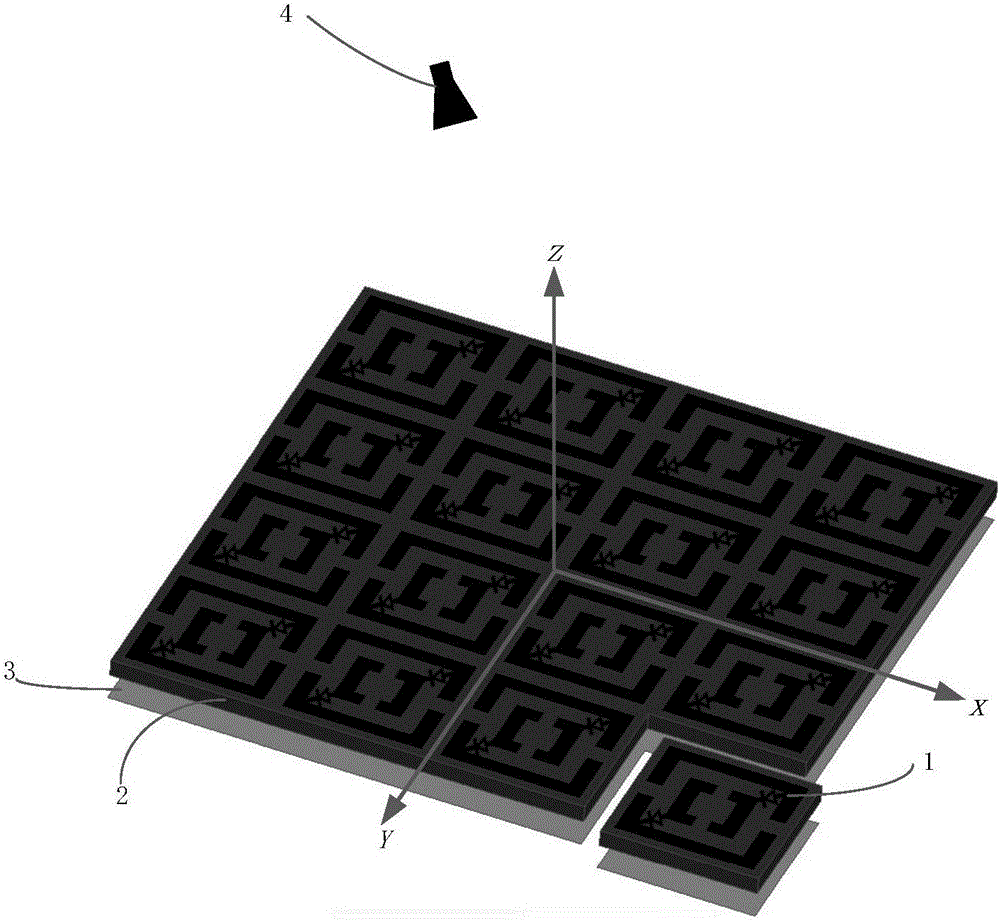
[0023] Refer to attached figure 1 , the overall structure of the antenna of the present invention will be further described in detail.

[0024] The present invention includes a dielectric substrate 2, a reflective structure 3 and an antenna feed 4; the relative permittivity ε of the dielectric substrate 2 is between 2-10, the thickness h is between 1mm-3mm, and the upper surface of the dielectric substrate 2 is etched M ×N metal patch units 1 arranged periodically, the values ​​of M and N are integers, 1


PUM


Abstract

The invention discloses a dual-band dual-polarization wave-beam-controllable microstrip reflective array antenna. The dual-band dual-polarization wave-beam-controllable microstrip reflective array antenna comprises a dielectric substrate, a reflective structure and an antenna feed source, wherein M*N periodically-arranged metal patch units are etched on the upper surface of the dielectric substrate; M and N are integers, wherein M is greater than 1 and less than 50; N is greater than 1 and less than 50; the reflective structure is positioned on the lower surface of the dielectric substrate; a metal floor structure is adopted; and the antenna feed source is positioned in the upper half space of a radiation structure. By adoption of the dual-band dual-polarization wave-beam-controllable microstrip reflective array antenna, the problem that continuous wave-beam scanning cannot be realized by a conventional microstrip reflective array antenna which can only work in a single-band or single-polarization mode is solved; by employing the metal patch units and variable capacitance diodes, the dual-band dual-polarization wave-beam-controllable microstrip reflective array antenna realizes reconfigurable frequency, reconfigurable polarization and wave-beam continuous scanning, thereby satisfying requirements of a radar and a communication system on multifunctional caliber multiplexing; and therefore, the dual-band dual-polarization wave-beam-controllable microstrip reflective array antenna can be applied to the wireless communication field.

Description

technical field [0001] The invention belongs to the technical field of communication, and further relates to a dual-frequency dual-polarization beam controllable microstrip reflector array antenna in the field of electromagnetic field and microwave technology. The invention can be used in the microwave band, and the antenna can work in a dual-frequency dual-polarization mode, and is suitable for a modern multi-functional aperture multiplexing antenna system. Background technique [0002] The microstrip planar reflectarray antenna combines some of the advantages of the traditional parabolic antenna and the large phased array antenna. It has the advantages of simple structure, low loss, easy integration, low cost, high efficiency, and precise control of the beam. It can be widely used in Radar, satellite communication and other fields. With the continuous development and improvement of electronic wireless communication technology, both radar and communication systems expect a...

Claims


Application Information

Patent Timeline
Patent Type & Authority Applications(China)
IPC IPC(8): H01Q3/44H01Q15/14H01Q19/10H01Q13/02
CPCH01Q3/44H01Q13/02H01Q15/148H01Q19/104
Inventor 李龙田顺成刘海霞刘肖肖翟会清史琰
Owner XIDIAN UNIV
Why Eureka
Try Eureka