Cylindrical layered luneberg lens

A columnar and lens technology, which is applied in the field of electromagnetic lenses, can solve the problems of impossibility, difficult control of dielectric constant, and degradation of lens performance, and achieve the effects of stabilizing electromagnetic scattering characteristics, avoiding reflection, and low cost

Active Publication Date: 2016-12-07
CHENGDU UNIV OF INFORMATION TECH
View PDF9 Cites 27 Cited by
  • Summary
  • Abstract
  • Description
  • Claims
  • Application Information

AI Technical Summary

Problems solved by technology

So far, the research of Lunbo lens antenna has achieved many phased results, but it is very difficult or even impossible to actually manufacture a dielectric sphere with a radius of R and realize the ideal change law of the dielectric constant realized
There are still many deficiencies in the Longbo lens antenna manufactured by the prior art, which are mainly reflected in the following aspects: First, the traditional method uses multi-layer dielectric filling materials or foaming technology to construct the Longbo lens, but there is a dielectric constant Difficult to control, difficult to achieve uniformity and other shortcomings, which seriously affect the radiation performance of Longbo lens antenna. For example, for foaming technology, the material used is mostly polystyrene foam. Theoretically, the internal radiation can be controlled by controlling the foam density. Air volume fraction, however, if the volume of the microscopic foam in the manufacturing process changes too large or too sma

Method used


Image

  • Cylindrical layered luneberg lens
  • Cylindrical layered luneberg lens
  • Cylindrical layered luneberg lens

Examples


Embodiment

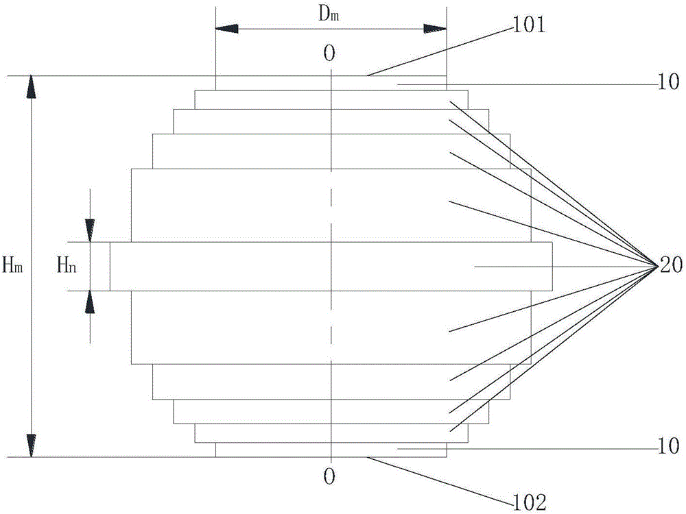
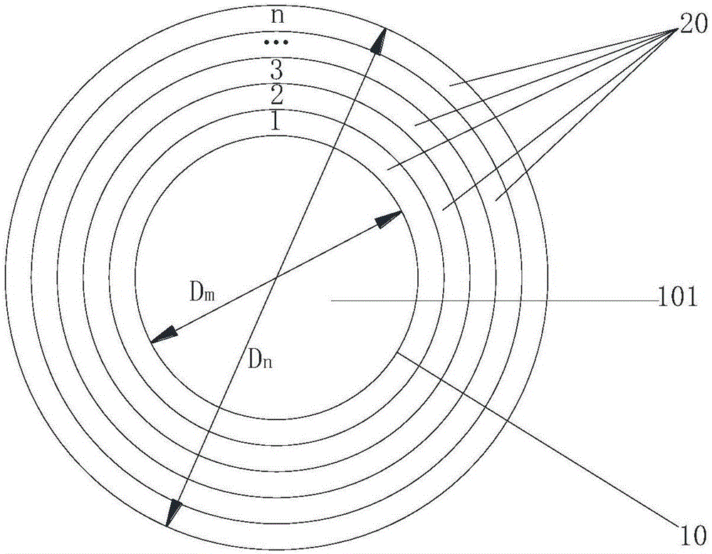
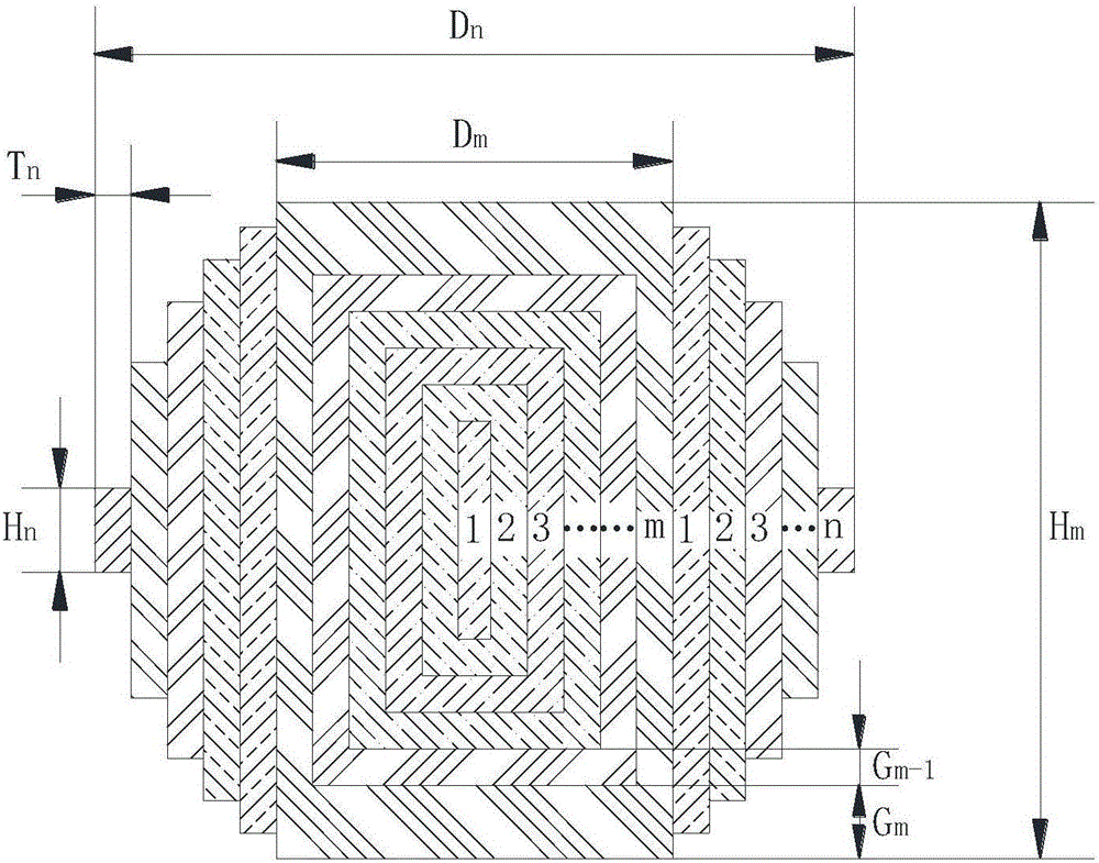
[0031] In this example, the columnar layered Lunberg lens includes two parts: the core and the cylinder, such as Figure 4 As shown, the column core in this example is composed of 7 nested cylinders, that is, the column core has a 7-layer structure, corresponding to m=7. The cylinder of this example includes 5 layers of cylinders sleeved in the middle of the column core, namely n=5. Depend on Figure 4 It can be seen that the lens in this example has a total of 12 layers from the innermost cylinder to the outermost cylinder. The radius of the innermost cylinder of the column core is 5mm (diameter is 10mm), and the radius of the subsequent outer cylinder is gradually increased to the outermost cylinder radius of 60mm (that is, Dn=120mm) according to the rule of increasing 5mm each time. In this example, both the thickness of the cylinder and the cylinder Ti are 5mm, and the maximum diameter of the lens is 120mm. In the column core of this example, the height of the innermost...


PUM


Abstract

The invention relates to an electromagnetic lens, and discloses a cylindrical layered luneberg lens. The cylindrical layered luneberg lens comprises a cylinder core and n layers of drums, wherein the cylinder core comprises m nested cylinders, and the heights and the diameters of the cylinders from the cylinder at the innermost side to the cylinder at the outermost side are progressively increased; the n layers of drums surround the middle part of the cylinder at the outermost side, the height of the drum at the innermost layer is smaller than that of the cylinder at the outermost side, and the heights of the drums from the drum at the innermost layer to the drum at the outermost layer are progressively decreased and the diameters are progressively increased; the dielectric constants from the cylinder at the innermost side of the cylinder core to the drum at the outermost layer are progressively decreased; and m and n are natural numbers. The cylindrical layered luneberg lens is a rotating body and a straight line through the circle centers of the top surface and the bottom surface of the cylinder core is a rotating shaft of the rotating body. The luneberg lens with the structure is divided into multiple layers in the axial direction and the radial direction. Each cylinder and each layer of drum are prepared from materials with different dielectric constants, so that progressive decreasing changes of the dielectric constants can be achieved along the axial direction and the radial direction of the rotating shaft; and the electromagnetic wave transmission characteristics are closer to those of an ideal luneberg lens.

Description

technical field [0001] The invention relates to an electromagnetic lens, in particular to a columnar layered Lunberg lens. Background technique [0002] A lens is a typical device in the field of optics that aggregates or disperses light. After the optical principle is extended to the field of electromagnetic radiation, the devices that change the incident electromagnetic field distribution into the required electromagnetic field distribution in a broad sense are lenses or lens antennas. The Luneberg lens is a widely used electromagnetic lens. The ideal Luneberg lens is a centrosymmetric dielectric sphere composed of inhomogeneous dielectric materials. Its dielectric constant has a special variation law and satisfies the relationship: Where εr is the dielectric constant of a spherical shell with radius r, and R is the radius of the dielectric sphere. It can be seen that the dielectric constant at the center of the sphere (r=0) is 2, and the dielectric constant on the sphe...

Claims


Application Information

Patent Timeline
IPC IPC(8): H01Q15/08
CPCH01Q15/08
Inventor 杜国宏孙浩然
Owner CHENGDU UNIV OF INFORMATION TECH
Why Eureka
Try Eureka